Superconducting magnet coil system with quench protection

a superconducting magnet coil and protection technology, applied in the direction of superconducting magnets/coils, emergency protective arrangements for limiting excess voltage/current, magnetic materials, etc., can solve problems such as non-ideally compensated current and dipole moment development, and achieve low dielectric strength, high voltage, and simple construction

Active Publication Date: 2008-01-10
BRUKER BIOSPIN
View PDF6 Cites 9 Cited by
  • Summary
  • Abstract
  • Description
  • Claims
  • Application Information

AI Technical Summary

Benefits of technology

[0013] The inventive magnet coil system is subdivided such that the sections are conventionally protectively wired in the area of the magnet coil system which could be damaged by high voltages. The sections of the magnet coil system, however, which are decisive with respect to stray field compensation are combined as a common block and protected by one single resistance or diode. The main field coil is thereby divided into two areas, i.e. into radially inner sections and radially outer sections. The radially inner sections of the main field coil only minimally contribute to the overall dipole moment of the main field coil and are bridged by at least one resistance. The outer sections of the main field coil which carries the major part of the overall dipole moment of the main field coil, are short-circuited with the shielding coil and protected by one single resistance. Since the dipole moment of the shielding coil is equal to the overall dipole moment of the main field coil but has a negative sign, the overall dipole moment of the main field coil is not compensated for by 100% with this wiring in case of a quench, but the plurality of expensive bridge circuits, disclosed in U.S. Pat. No. 5,644,233, can be omitted. The non-ideally compensated current and dipole moment development in case of a quench produces slight, but assessable, stray field changes which are within tolerable limits. This correction can be taken into consideration for determining the stray field specification. The increased voltages in the outer sections of the main field coil and in the shielding coil during a quench may be accepted due to the relatively high dielectric strength of the second superconducting material. The inventive magnet coil system may therefore have a simple construction, wherein in case of a quench, only small excess stray fields occur, and high voltages are generated only at locations where they can be handled.
[0014] In a preferred embodiment, the first superconducting material contains Nb3Sn and the first voltage insulation comprises a glass fiber or ceramic fiber insulation. The glass fiber or ceramic fiber insulation has low dielectric strength with respect to high electric voltages since it normally contains carbon to render the glass fiber or ceramic fiber insulation more ductile for winding, and due to the open weave structure. When these materials are used, the above-described protective wiring of the inner sections comprising the first superconducting material nevertheless prevents damage to the sections due to voltage breakdown.

Problems solved by technology

The non-ideally compensated current and dipole moment development in case of a quench produces slight, but assessable, stray field changes which are within tolerable limits.

Method used


Image

  • Superconducting magnet coil system with quench protection
  • Superconducting magnet coil system with quench protection
  • Superconducting magnet coil system with quench protection

Examples


Embodiment Construction

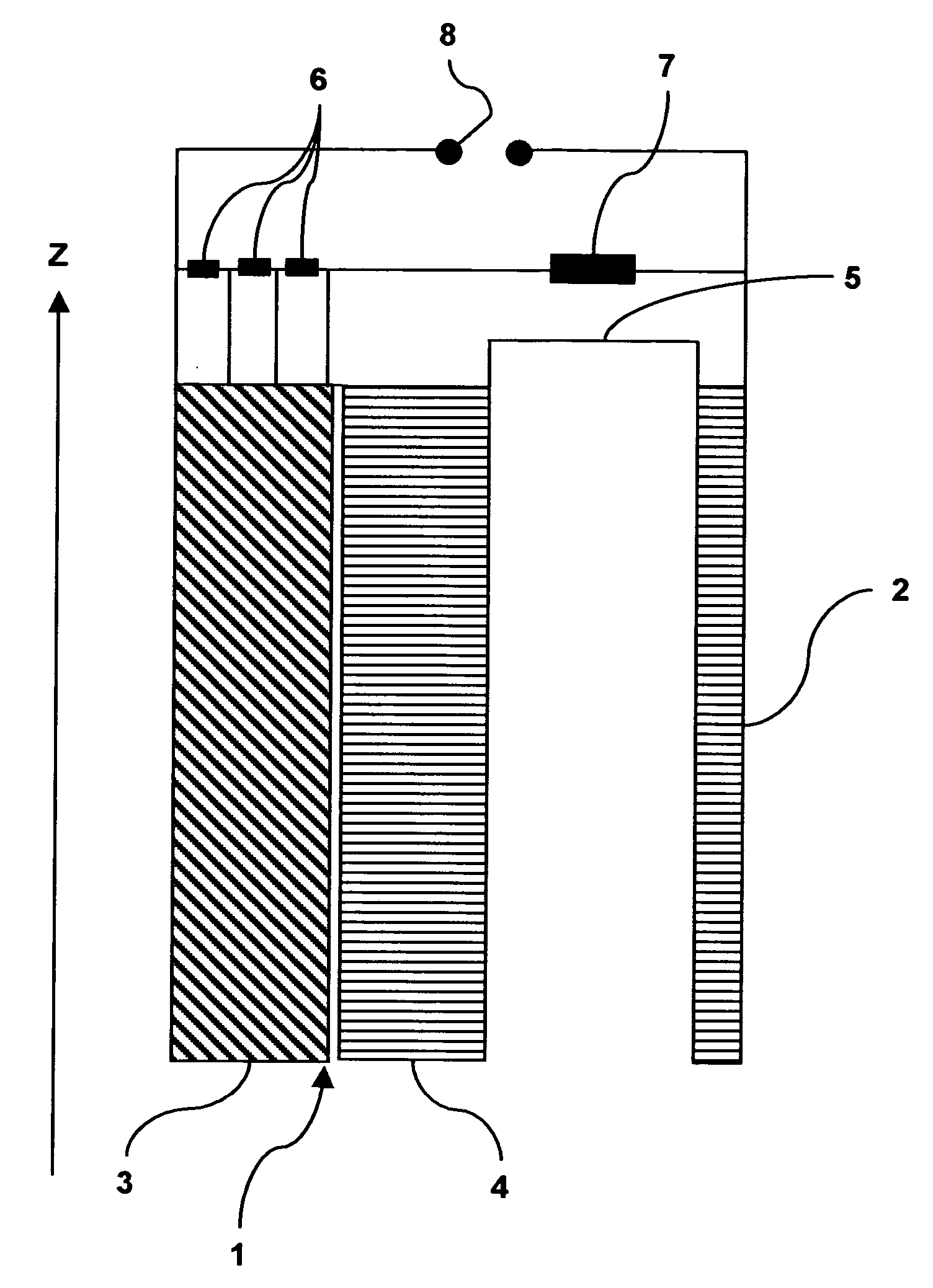
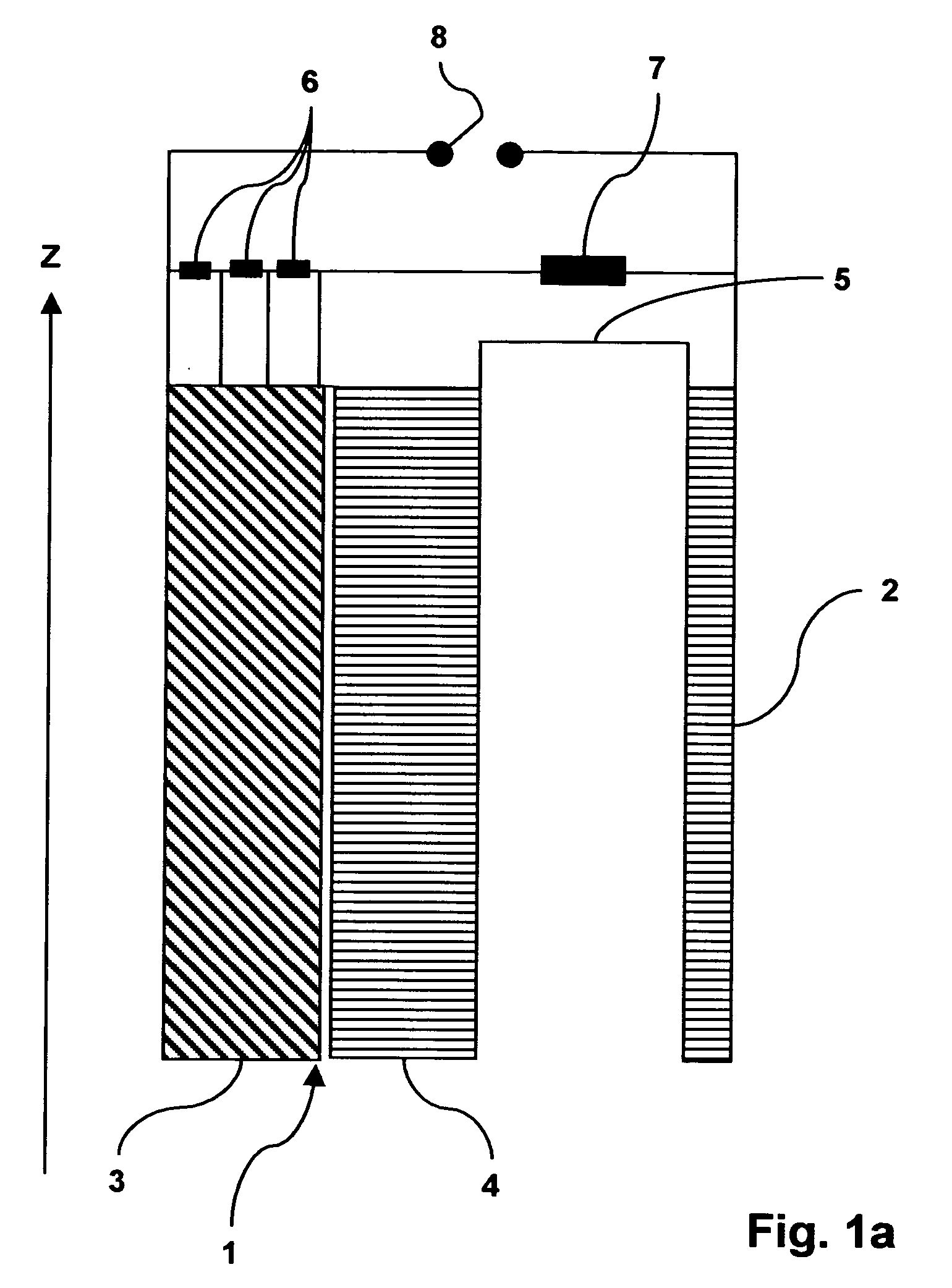
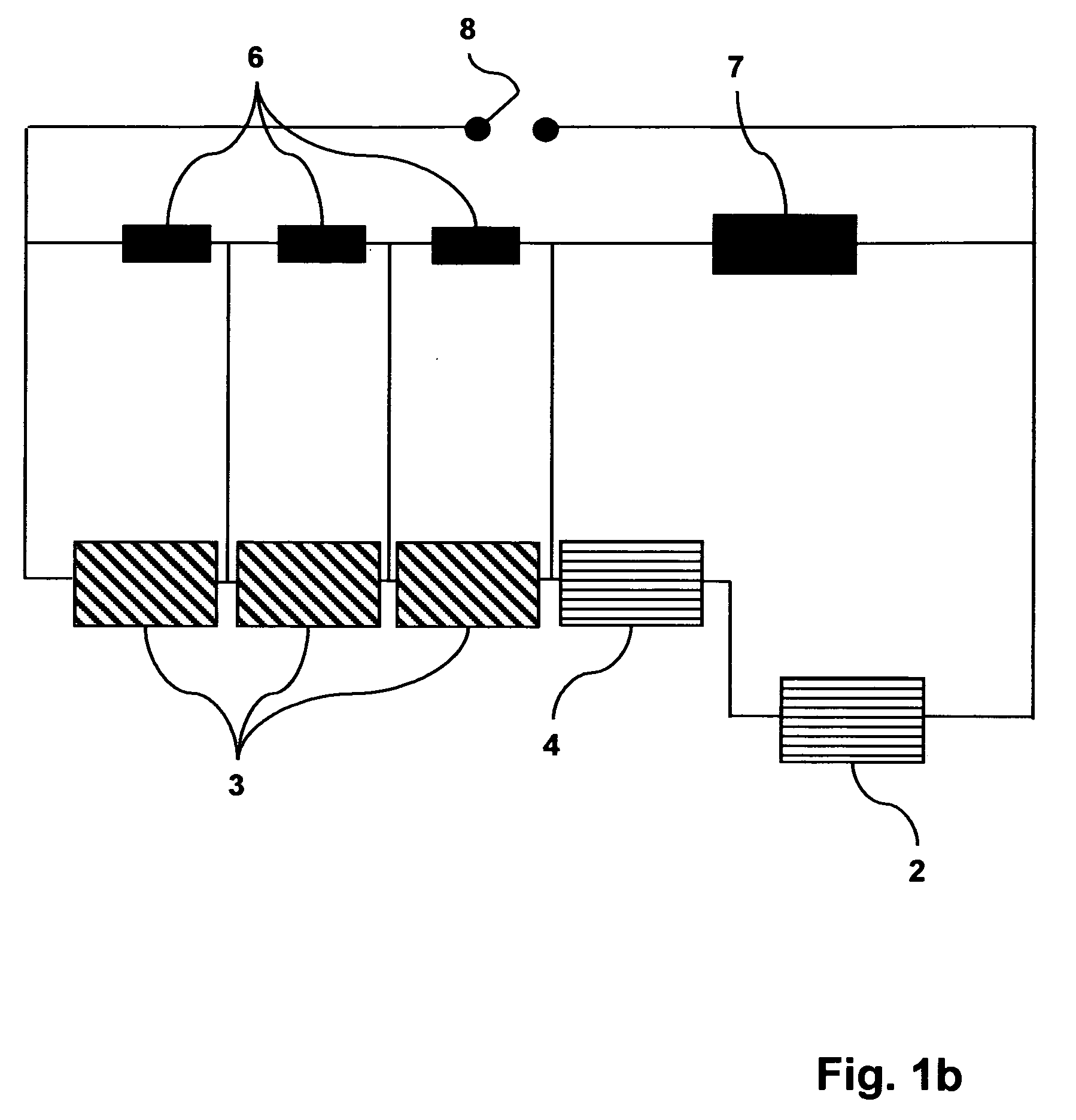
[0027]FIG. 1a shows an inventive magnet coil system with a main field coil 1, disposed about the axis z, and a shielding coil 2 which radially surrounds the main field coil 1. FIG. 1b shows a wiring diagram of this magnet coil system. The main field coil and the shielding coil may be short-circuited via a superconducting main switch 8. The main field coil 1 is divided into radially inner sections 3 and radially outer sections 4. The main field coil 1 and the shielding coil 2 are connected in series via an electric connection 5. The inner sections 3 of the embodiments of FIGS. 1a and 1b are divided into three areas which are each bridged by an ohmic resistance 6. This prevents excess voltages in the area of the inner sections 3. The areas of the magnet coil system which are decisive for stray field compensation, i.e. the outer sections 4 and the shielding coil 2 are, in contrast thereto, commonly protected by one single further resistance 7. The voltage may increase during a quench w...


PUM

PropertyMeasurementUnit
voltageaaaaaaaaaa
electric voltage insulationaaaaaaaaaa
critical magnetic fieldaaaaaaaaaa

Abstract

A superconducting magnet coil system comprising a main field coil which is formed from series-connected sections, wherein the conductors of the radially inner sections contain a first superconducting material and have first electric voltage insulation, the conductors of the radially outer sections comprise a second superconducting material and are provided with second electric voltage insulation, wherein the first superconducting material has a higher critical magnetic field than the second superconducting material, and the first voltage insulation has a smaller dielectric strength than the second voltage insulation, and a shielding coil which is connected in series with the main field coil, radially surrounds the main field coil, and comprises conductors of the second superconducting material having the second electric voltage insulation, wherein the main field coil and the shielding coil are superconductingly short-circuited during operation and are protected through several ohmic resistances and / or diodes in case of a quench, is characterized in that the inner sections are protected by at least one ohmic resistance and the outer sections are protected, together with the shielding coil, by one single ohmic resistance.

Description

[0001] This application claims Paris Convention priority of DE 10 2005 047 938.3 filed Oct. 6, 2005 the complete disclosure of which is hereby incorporated by reference. BACKGROUND OF THE INVENTION [0002] The invention concerns a superconducting magnet coil system with a main field coil which is formed from radially nested, series-connected sections comprising conductors, wherein the conductors of the radially inner sections contain a first superconducting material, and have a first electric voltage insulation, the conductors of the radially outer sections comprising a second superconducting material and having a second electric voltage insulation, wherein the first superconducting material has a higher critical magnetic field than the second superconducting material and the first voltage insulation has, at least in certain areas, a smaller dielectric strength than the second voltage insulation, and with a shielding coil which is connected in series with the main field coil, radiall...

Claims


Application Information

Patent Timeline
Patent Type & Authority Applications(United States)
IPC IPC(8): H01F6/00
CPCG01R33/3815H01F6/02G01R33/421
Inventor FRANTZ, WOLFGANG
Owner BRUKER BIOSPIN
Why Eureka
Try Eureka