Ultrasonic doppler diagnostic apparatus, and method of controlling ultrasonic doppler diagnostic apparatus

Active Publication Date: 2008-01-10
TOSHIBA MEDICAL SYST CORP
View PDF3 Cites 15 Cited by
  • Summary
  • Abstract
  • Description
  • Claims
  • Application Information

AI Technical Summary

Benefits of technology

[0024]It is therefore an object of the present invention to provide an ultrasonic Doppler diagnostic apparatus and a method of controlling the ultrasonic Doppler diagnostic apparatus, the ultrasonic Doppler diagnostic apparatus being equipped

Problems solved by technology

However, this method is an invasive method and thus has many restrictions.
Although this is a noninvasive method, the burden on a patient is too heavy.
Therefore, it is often impossible to accurately select and extract the image indicating, for example, the peak flow velocity value.
This has been a heavy burden both emotionally and physically.
Moreover, it is impossible to evaluate the coronary flow reserve in real time, and it is necessary, after an inspection (ultrasonic scan)

Method used


Image

  • Ultrasonic doppler diagnostic apparatus, and method of controlling ultrasonic doppler diagnostic apparatus
  • Ultrasonic doppler diagnostic apparatus, and method of controlling ultrasonic doppler diagnostic apparatus
  • Ultrasonic doppler diagnostic apparatus, and method of controlling ultrasonic doppler diagnostic apparatus

Examples


Example

First Embodiment

[0065]First, a first embodiment of the present invention will be described.

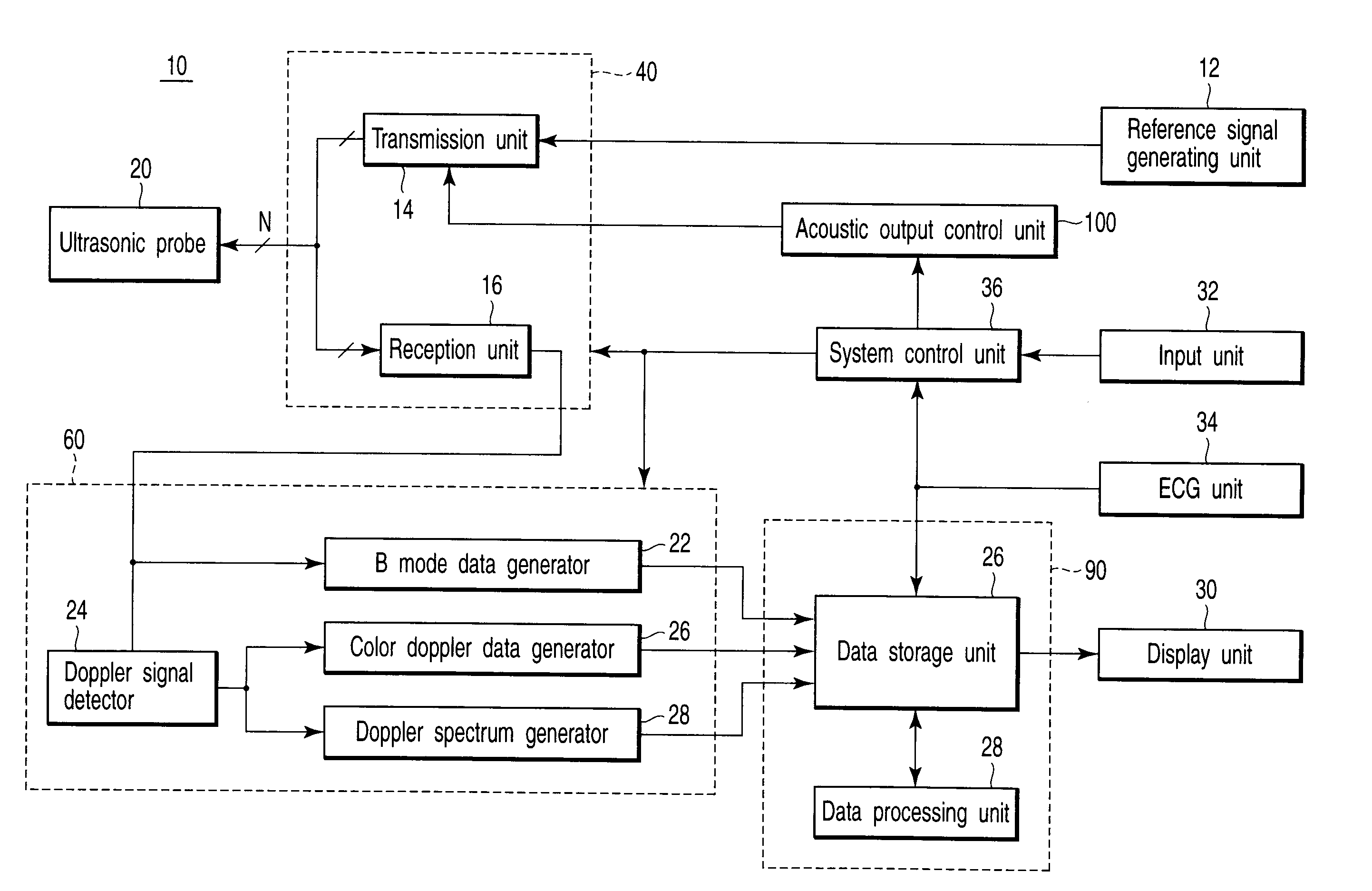
[0066]FIG. 6 is a block diagram showing the entire configuration of an ultrasonic Doppler diagnostic apparatus in the present embodiment, and FIG. 7 is a block diagram showing the configurations of a transmission / reception unit and a data generating unit constituting the ultrasonic diagnostic apparatus.

[0067]In FIG. 6, an ultrasonic Doppler diagnostic apparatus 10 comprises an ultrasonic probe 20, a transmission / reception unit 40, a data generating unit 60, a data processing / storage unit 90, and a display unit 30.

[0068]The ultrasonic probe 20 sends / receives ultrasonic waves to / from an unshown specimen. The transmission / reception unit 40 sends / receives electric signals to / from the ultrasonic probe 20. Moreover, the data generating unit 60 processes the received signal obtained from the transmission / reception unit 40, and generates B mode data, color Doppler data, and a Doppler spectrum.

[0069]Th...

Example

[0100]Next, a second embodiment of the present invention will be described.

[0101]In the first embodiment, the display unit 30 only displays a locus curve in a time direction of the peak flow velocity value at every heartbeat of the blood flow in the left anterior descending coronary artery. However, in the second embodiment, the locus curve is displayed in real time on the display unit 30 together with image displays in a B mode, a color mode and a PWD mode in order to increase the throughput of the whole inspection when the coronary flow reserve (CFR) is found.

[0102]In addition, the basic configuration and operation of the ultrasonic Doppler diagnostic apparatus 10 in the second embodiment described below are the same as those in the first embodiment described above, so that the same reference numerals are assigned to the same parts to avoid the repetition of explanation, and different parts alone will be described while the same parts are neither shown in the drawings nor describe...


PUM


Abstract

An ultrasonic Doppler diagnostic apparatus sends ultrasonic waves to a specimen, receives a reflection signal of the ultrasonic waves from the specimen to detect a Doppler signal, obtains blood flow information indicating a peak flow velocity of coronary blood flow, and displays the flow velocity information before and after the administration of a drug to the specimen on a display unit. Then, at least velocity ranges of the flow velocity information before and after the administration of the drug to the specimen are adjusted, and during an ultrasonic scan of the specimen, data on a plurality of acquired images having different velocity ranges are adjusted to the same velocity range. A system control unit displays the data on the plurality of images adjusted to the same velocity range on the display unit.

Description

CROSS-REFERENCE TO RELATED APPLICATIONS[0001]This application is based upon and claims the benefit of priority from prior Japanese Patent Application No. 2006-155065, filed Jun. 2, 2006, the entire contents of which are incorporated herein by reference.BACKGROUND OF THE INVENTION[0002]1. Field of the Invention[0003]The present invention relates to an ultrasonic Doppler diagnostic apparatus, and more particularly, it relates to an ultrasonic Doppler diagnostic apparatus used to diagnose the function of a specimen on the basis of a change in velocity information over time within the specimen, and to a method of controlling the ultrasonic Doppler diagnostic apparatus.[0004]2. Description of the Related Art[0005]A coronary flow reserve is used as an index indicating the ability to increase a coronary blood flow in accordance with an increase in myocardial oxygen consumption, and is shown by a ratio of a coronary blood flow value at peak coronary dilatation to a coronary blood flow at re...

Claims


Application Information

Patent Timeline
IPC IPC(8): A61B8/00
CPCA61B8/06
Inventor TAKIMOTO, MASAOKATAGUCHI, MUNEKIKAKEE, AKIHIROIMAMURA, TOMOHISASAKAGUCHI, FUMIYASUSUMI, ATSUSHI
Owner TOSHIBA MEDICAL SYST CORP
Why Eureka
Try Eureka