
Control Valve for a Servo Steering System

a technology of servo steering and control valve, which is applied in the direction of power steering steering, steering parts, couplings, etc., can solve the problems of high steering resistance, high cost, and unreliability of alternative measures such as a control circuit comprising a pressure measurement means or a more markedly differentiated activation of the servo valv

Inactive Publication Date: 2008-01-17
THYSSENKRUPP PRESTA STEERTEC
View PDF4 Cites 3 Cited by
  • Summary
  • Abstract
  • Description
  • Claims
  • Application Information

AI Technical Summary

Benefits of technology

[0005]As a result of the fact that the free cross section or passage area of the opening structure does not depend linearly on the deflection of the valve slide, purposeful influencing of the hydraulic pressure applied to the pressure bodies is facilitated over a relatively large range merely on account of the shaping of the opening structure. Overall, a control valve according to the invention can have a greater influence, in a greater pressure range, on the steering characteristics of a servo steering system than is possible by a pressure-limiting control valve according to the prior art.
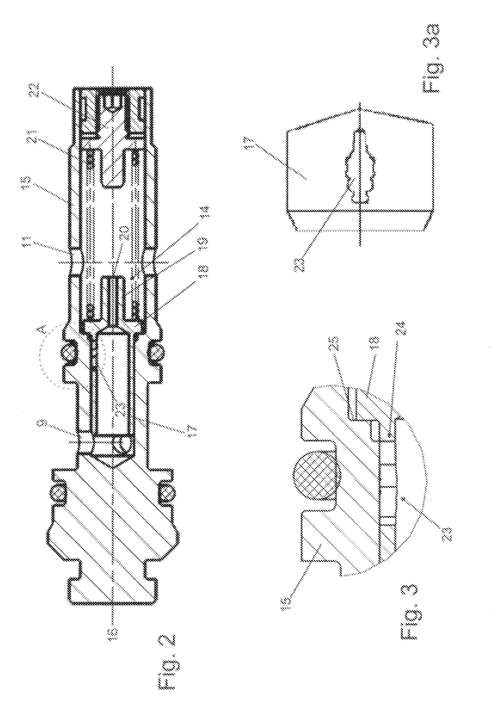
[0006]In a preferred embodiment, the valve slide has a hollow cylindrical portion, the opening structure being in the form of an aperture in a wall of the portion. A control valve of this type can be manufactured easily and cost-effectively. Particularly preferably, the guide has in this case at least two cylindrical portions having differing diameters, the cover being in the form of a stepped edge of the guide. Also preferably, the cover has in this case a control edge, the control edge being oriented substantially perpendicularly to the cross-sectional surface or area of the opening structure. Overall, the control valve can be manufactured easily in this way, having at the same time reliable regulation and effective sealing when completely closed. Alternatively, the control edge can also be oriented at an angle to the cross-sectional area of the opening other than a right angle.
[0007]Generally preferably, the supporting force of a control valve according to the invention is brought about by a spring supporting the valve slide against the guide. In conjunction with adjustability of the resilient force, this provides in a simple manner, in particular, a well-defined operating point of the control valve.
[0008]A preferred detailed embodiment makes provision for the cover completely to close the opening structure below a minimum pressure. Alternatively, provision may also be made for the opening structure to have a residual opening even in a pressureless state. However, a constant orifice is preferably provided for this purpose in the valve slide, in addition to the opening structure, the constant orifice providing a permanent connection of the inlet and outlet. A constant orifice of this type allows additional precise correction of the hydraulic pressure acting on the pressure body to be provided.
[0011]The invention also relates to a servo steering system mentioned at the outset for a motor vehicle, the servo steering system comprising, in accordance with the invention, a control valve as defined. This allows the steering characteristics of the servo steering system to be advantageously influenced, using simple means, at various speeds.

Problems solved by technology

Overall, this means that adjustment can be carried out only insufficiently specifically in the regions of relatively high speed, in which a relatively high steering resistance is required.
Alternative measures such as a control circuit comprising a pressure-measuring means or a more markedly differentiated activation of the servo valve are expensive and unreliable on account of their complexity.
This allows desired corrections in the response characteristics of the control valve to be provided compared to the prior art, so the control valve provides initially merely a slight drop in pressure but, as the pressure rises, increasingly more marked limitation of the pressure by an increasingly large volume flow rate of the diverted hydraulic liquid.

Method used


Image

  • Control Valve for a Servo Steering System
  • Control Valve for a Servo Steering System
  • Control Valve for a Servo Steering System

Examples


Embodiment Construction

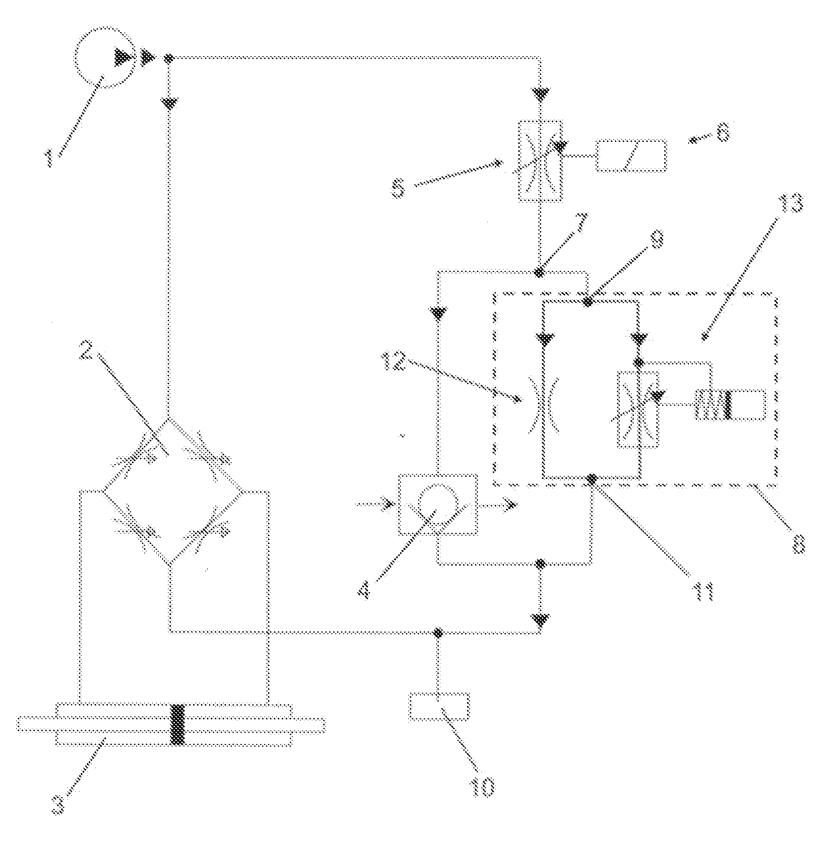
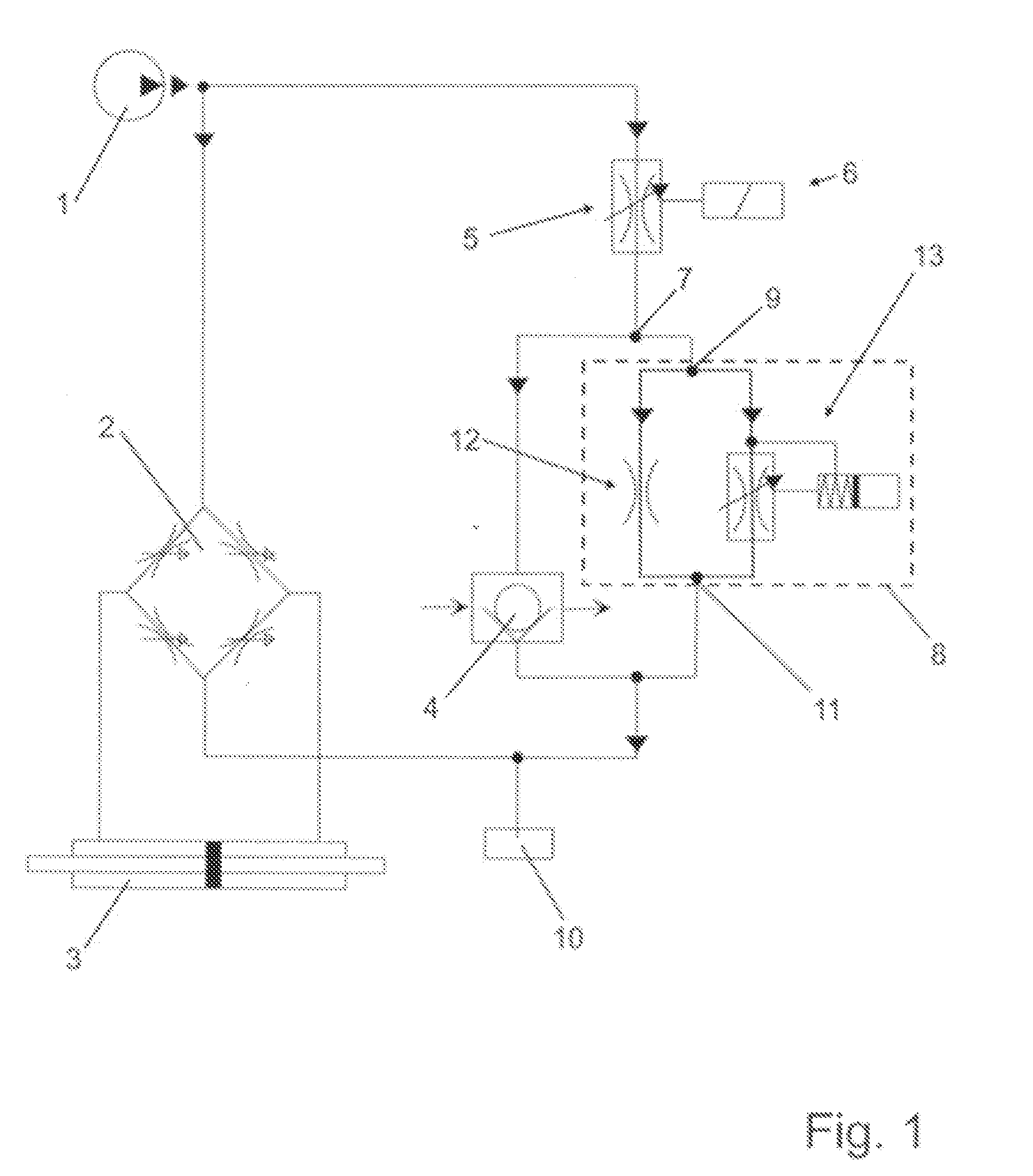
[0019]The schematic hydraulic circuit diagram of a servo steering system as shown in FIG. 1 is known. A hydraulic liquid under pressure is supplied, using a pump 1, to a rotary slide valve 2 which is connected to a manually actuated steering wheel of a motor vehicle via a steering column. In the present case, the rotary slide valve has an open center such as is substantially described in DE 10 2004 04 641 A1.

[0020]Depending on the torque applied between the steering wheel and a steering gear, the rotary slide valve 2 opens hydraulic lines to a hydraulic servo motor 3. The dependency of this opening or of the pressure differential applied to the servo motor on the torque is referred to, in the present case, as the steering characteristics of the servo steering system. The present servo steering system has steering characteristics which are variable as a function of speed, the rotary slide valve 2 being provided with a reactive arrangement. This reactive arrangement comprises pressure...


PUM


Abstract

A control valves for a servo steering system, having an inlet for supplying a hydraulic liquid at a first pressures and an outlet for discharging the hydraulic liquid into a region having a smaller, second pressure, especially into a pressureless reservoir. The control valve has a guide and a valve slide accommodated in the guide so as to be movable therein along an axis. The valve slide is acted upon on one side by the hydraulic liquid with the first pressure and on the opposite side by a defined supporting force. An opening structure is provided on at least one of the valve slide and guide. A cover corresponding to the opening structure is provided on the other of the guide and valve slide. A movement of the valve slide relative to the guide effects a change of a free passage area of the opening structure that is not closed off by the cover, whereby the hydraulic liquid is able to flow from the inlet, through the free passage area, to the outlet. The opening structure has a defined shape such that the free passage area of the opening structure does not depend linearly on the movement of the valve slide

Description

BACKGROUND OF THE INVENTION[0001]The present invention relates to a control valve for a servo steering system, and to a servo steering system for a motor vehicle.[0002]DE 10 2004 044 641 A1 describes a servo steering system for a motor vehicle, in which a rotary slide valve is provided with a reactive arrangement for activating a hydraulic servo motor. The reactive arrangement comprises hydraulically acted-on pressure bodies which depending on the degree of pressure applied, bring about increasing rigidity of the steering system or increased moment resistance of the rotary slide valve. For regulating the pressure of the reactive arrangement, it is know to provide an electrically activated servo valve which regulates the volume flow rate and hence the pressure acting on the reactive arrangement. A control valve is connected in parallel to the reactive unit for limiting pressure. In this known control valve, a hydraulically acted-on valve slide has an opening surface which is rectangu...

Claims


Application Information

Patent Timeline
IPC IPC(8): F16D31/02
CPCB62D5/062F15B11/006F15B11/028F15B11/0423F15B2211/20538F15B2211/30575F15B2211/7053F15B2211/40515F15B2211/50536F15B2211/513F15B2211/526F15B2211/6052F15B2211/40507
Inventor ULBRICHT, THOMASBREUNING, EDWIN
Owner THYSSENKRUPP PRESTA STEERTEC
Learn More