Air-conditioning system for vehicle

a technology for air-conditioning systems and vehicles, applied in refrigeration machines, light and heating equipment, transportation and packaging, etc., can solve the problems of unavoidable cost increase, and achieve the effect of reducing the fuel consumption of the engine, and reducing the amount of input energy

Inactive Publication Date: 2008-01-17
DENSO CORP
View PDF8 Cites 30 Cited by
  • Summary
  • Abstract
  • Description
  • Claims
  • Application Information

AI Technical Summary

Benefits of technology

[0009]As either one of the heat sources, for which the input energy amount for the unit cooling capacity is smaller than that for the other heat source, is preferentially used for performing the cooling operation, an energy amount for the air-conditioning operation can be reduced. In addition, the multiple heat sources can be effectively used.
[0011]As either one of the driving sources, for which the input energy amount for the unit cooling capacity is smaller than that for the other heat source, is preferentially used for performing the cooling operation, an energy amount for the air-conditioning operation can be reduced. In addition, the multiple driving sources can be effectively used.
[0015]In the above air-conditioning system, there are two driving sources for the compressor (e.g. the engine and the electric motor) An increased amount of fuel, which is necessary for driving the compressor, depends on the operation point of the engine, when the engine is used as the driving source for the compressor. Accordingly, it may occur depending on the current operation point of the engine, that the input energy amount can be smaller when the other driving source (e.g. the electric motor) is used than the case of using the engine. According to the feature of the present invention, the other driving source (the electric motor) is selectively used depending on the situation (an operational, condition of the engine and / or vehicle, and other surrounding conditions), even in the case that the compressor can be driven by the engine. As a result, the input energy, that is the fuel consumption by the engine can be reduced.

Problems solved by technology

Although each of the above conventional air-conditioning systems has a function of continuing the cooling operation during the engine operation is stopped, cost increase is not avoidable because an additional component is necessary.
The above problem (relatively smaller effect for a large number of components) commonly exists not only in the above air-conditioning systems but also in a vehicle air-conditioning system having multiple thermal sources (for heat of cooling) or in a vehicle air-conditioning system having a compressor operated by multiple driving sources.

Method used


Image

  • Air-conditioning system for vehicle
  • Air-conditioning system for vehicle
  • Air-conditioning system for vehicle

Examples


first embodiment

[0035]An air-conditioning system according to a first embodiment will be explained with reference to the drawings.

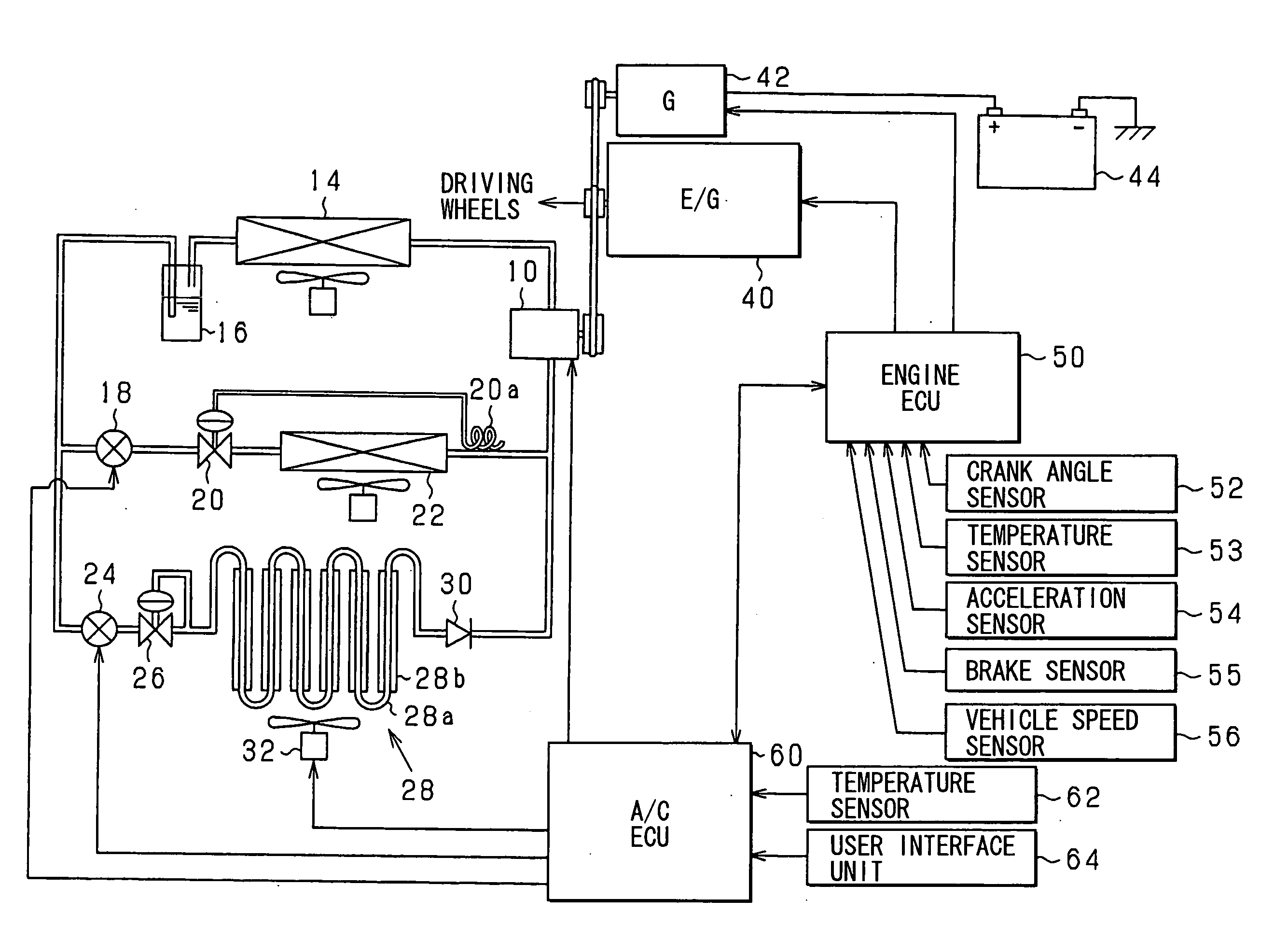
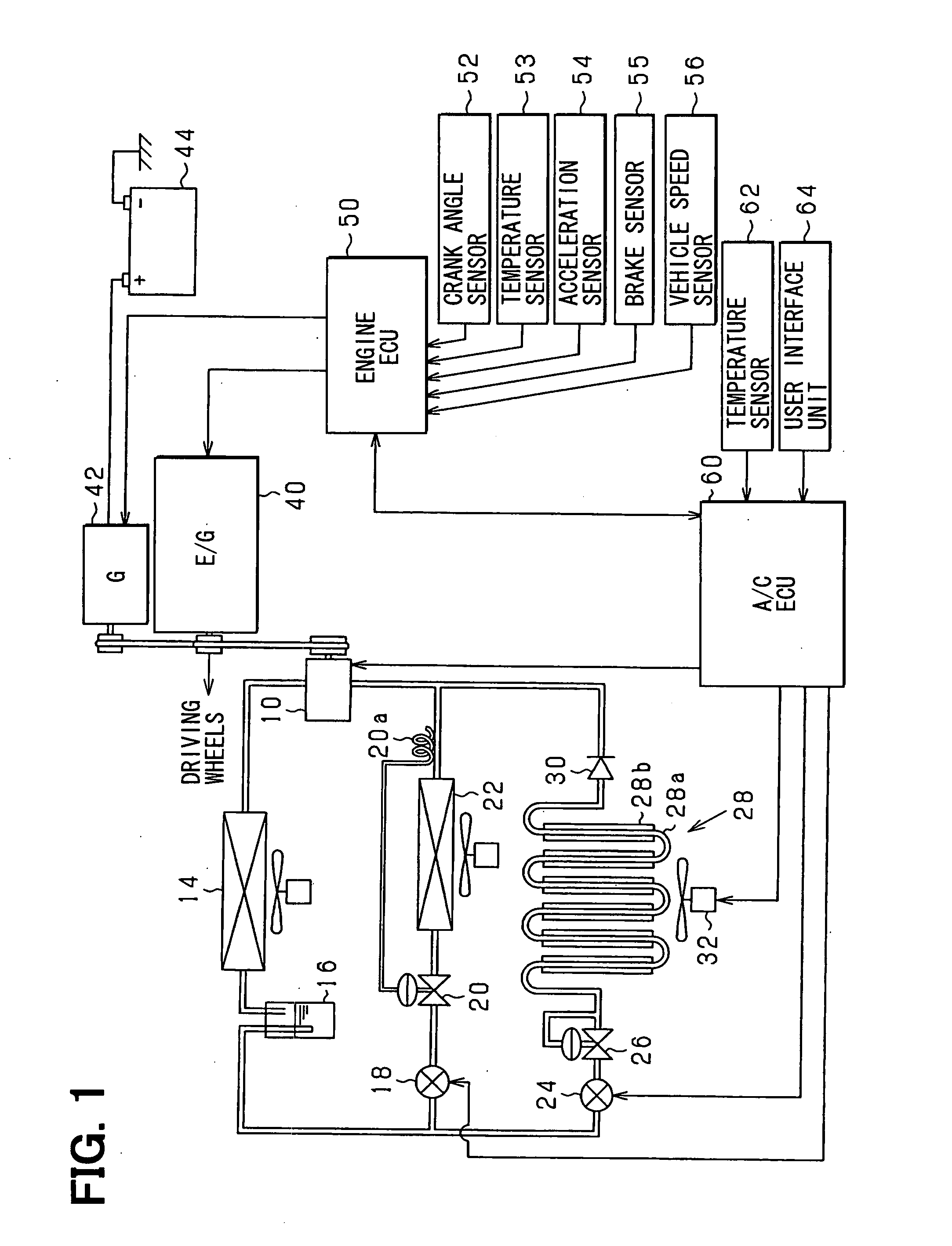
[0036]FIG. 1 is a schematic view showing a system structure of an air-conditioning system for a vehicle according to the first embodiment of the present invention.

[0037]As shown in FIG. 1, refrigerant is compressed by a capacity variable type compressor 10 and supplied to a condenser 14. The refrigerant is then supplied to a receiver 16 for separating the refrigerant into liquid-phase and gas-phase refrigerant and temporally storing the liquid-phase refrigerant. The refrigerant of the receiver 16 is supplied to an expansion valve 20 of a temperature dependent type through an electromagnetic valve 18. The refrigerant is rapidly expanded by the expansion valve 20, so that the refrigerant is atomized. The atomized refrigerant is vaporized in an evaporator 22 through heat-exchange with outside air. A temperature sensing pipe 20a of the expansion valve 20 is provided at an ou...

second embodiment

[0069]A second embodiment will be explained with reference to the drawings, by focusing on different points from the first embodiment.

[0070]According to the second embodiment, the refrigerating cycle (the evaporator22) and the heat accumulator 28 are selectively used depending on the operation point of the engine 40, when the temperature of the vehicle inside air is controlled. More exactly, the refrigerating cycle and the heat accumulator 28 are selectively used depending on the rotational speed and the load (the torque) of the engine 40, in accordance with a map shown in FIG. 7.

[0071]FIG. 8 shows a flowchart for a process of controlling the temperature of the vehicle inside air according to the embodiment. The process of FIG. 8 is repeatedly carried out by the ECU 60 at a predetermined interval.

[0072]At first, the ECU 60 determines at a step S40, whether there is a command for cooling the vehicle inside air, based on the operations of the user interface unit 64 and / or the temperat...

third embodiment

[0080]A third embodiment will be explained with reference to the drawings, by focusing on different points from the first embodiment.

[0081]FIG. 9 shows a system structure of an air-conditioning system for a vehicle according to a third embodiment. The same reference numerals are used in the third embodiment for those parts, which are identical or similar to those of the first embodiment (FIG. 1). According to the embodiment, an electric motor 70 is provided as a driving source for driving the compressor 10 in addition to the engine 10 A solar battery 72 is further provided for the purpose of generating the electrical power which will be charged into the battery 44.

[0082]FIG. 10 shows a flowchart for a process of controlling the temperature of the vehicle inside air according to the embodiment. The process of FIG. 10 is repeatedly carried out by the ECU 60 at a predetermined interval.

[0083]At steps S50 to S56, the ECU 60 carries out the same processes to the steps S10 to S16 of FIG. ...


PUM


Abstract

In an air-conditioning system for a vehicle, which has multiple heat sources (an evaporator and a heat accumulator), either one of the heat sources, for which the input energy amount for the unit cooling capacity is smaller than that for the other heat source, is preferentially used for performing the cooling operation, an energy amount for the air-conditioning operation can be reduced.

Description

CROSS REFERENCE TO RELATED APPLICATION[0001]This application is based on Japanese Patent Application No. 2006-191166, which is filed on Jul. 12, 2006, the disclosure of which is incorporated herein by reference.FIELD OF THE INVENTION[0002]The present invention relates to an air-conditioning system for a vehicle.BACKGROUND OF THE INVENTION[0003]A conventional air-conditioning system for a vehicle is disclosed, for example, in Japanese Patent Publication No. H10-53019, which has a heat accumulator for storing heat of refrigerant (heat of cooling) in addition to an evaporator to which refrigerant compressed by a compressor is supplied. The compressor is driven by an internal combustion engine mounted on a vehicle. According to the conventional system, cooling operation can be continuously performed by use of the heat stored in the heat accumulator even during a period in which the engine operation is temporally stopped.[0004]Another conventional air-conditioning system is disclosed, fo...

Claims


Application Information

Patent Timeline
Patent Type & Authority Applications(United States)
IPC IPC(8): B60H1/32
CPCB60H1/00492B60H1/3211B60H1/04
Inventor OBAYASHI, KAZUYOSHITANI, KEISUKETANAKA, KATSUNORIYAMAMOTO, NAOKISHIMOYAMA, TAKESHIYAMASHITA, YUKIHIRO
Owner DENSO CORP
Why Eureka
Try Eureka