
Connecting lead wire for a solar battery module, method for fabricating same, and solar battery module using the connecting lead wire

a solar battery and solar panel technology, applied in the direction of pv power plants, other domestic articles, semiconductor devices, etc., can solve the problems of increasing manufacturing costs, increasing process complexity, increasing production efficiency, etc., and achieve the effect of reducing cost and improving production efficiency

Inactive Publication Date: 2008-01-17
HITACHI CABLE
View PDF11 Cites 18 Cited by
  • Summary
  • Abstract
  • Description
  • Claims
  • Application Information

AI Technical Summary

Benefits of technology

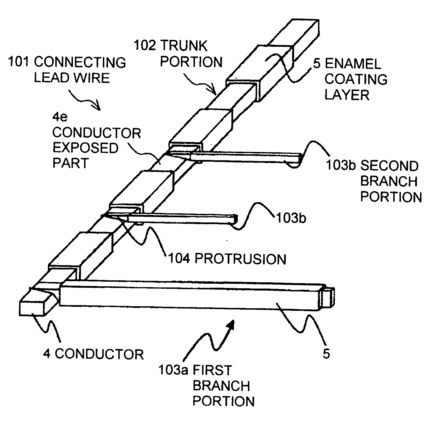
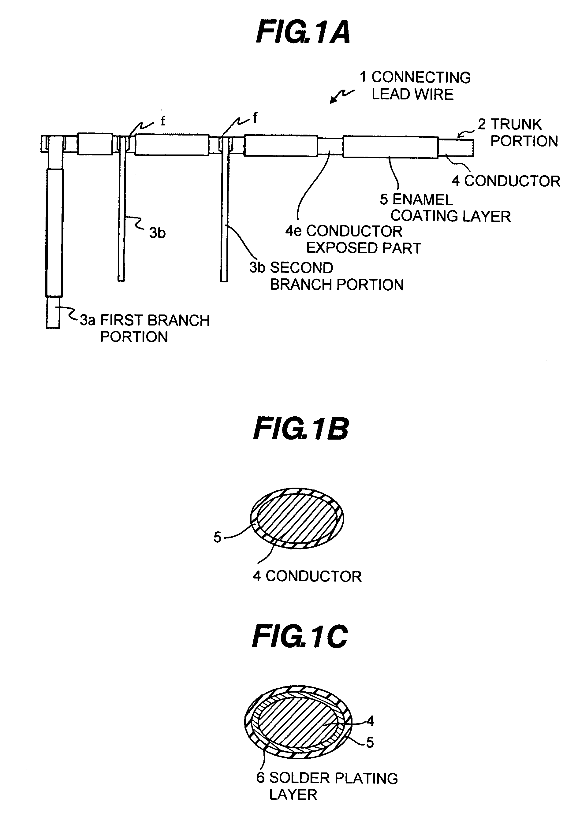
[0024] Accordingly, an object of the present invention is to provide a connecting lead wire for a solar battery module, a method for fabricating the same, and a solar battery module using the connecting lead wire, by which strings in the solar battery module are electrically connected with each other, an electrical insulation between the lead wires adjacently disposed is assured, and a production efficiency can be improved as well as a reduction in cost can be expected.
[0025] Further, another object of the present invention is to provide a connecting lead wire for a solar battery module, a method for fabricating the same, and a solar battery module using the connecting lead wire, by which a space for interconnection is assured enough, a freedom of layout can be improved, and a high density wiring can be expected.
[0059] According to the present invention, since an enamel wire is used as parts of the lead wire, it is not necessary to use the insulating film. Further, the manufacturing process can be reduced, as well as the electrical insulation between the adjacent lead wires can be surely expected.

Problems solved by technology

Particularly in the film adhering process, it is necessary to conduct a process of the temporary crimping and final crimping on a part of the insulating film one by one, so that the number of processes is increased and the process becomes complicated.
(ii) In the conventional device, it is necessary to stick a plurality of insulating films to each other, after manufacturing the semi-finished product 141 comprising the branch portion pieces and the trunk portion pieces, there by increasing the number of parts and components, so that a manufacturing cost is increased.
Accordingly, a space for interconnection is increased and a freedom of layout is limited.
Therefore, such a device is not suitable for the high density wiring.

Method used


Image

  • Connecting lead wire for a solar battery module, method for fabricating same, and solar battery module using the connecting lead wire
  • Connecting lead wire for a solar battery module, method for fabricating same, and solar battery module using the connecting lead wire
  • Connecting lead wire for a solar battery module, method for fabricating same, and solar battery module using the connecting lead wire

Examples


example

Example 1

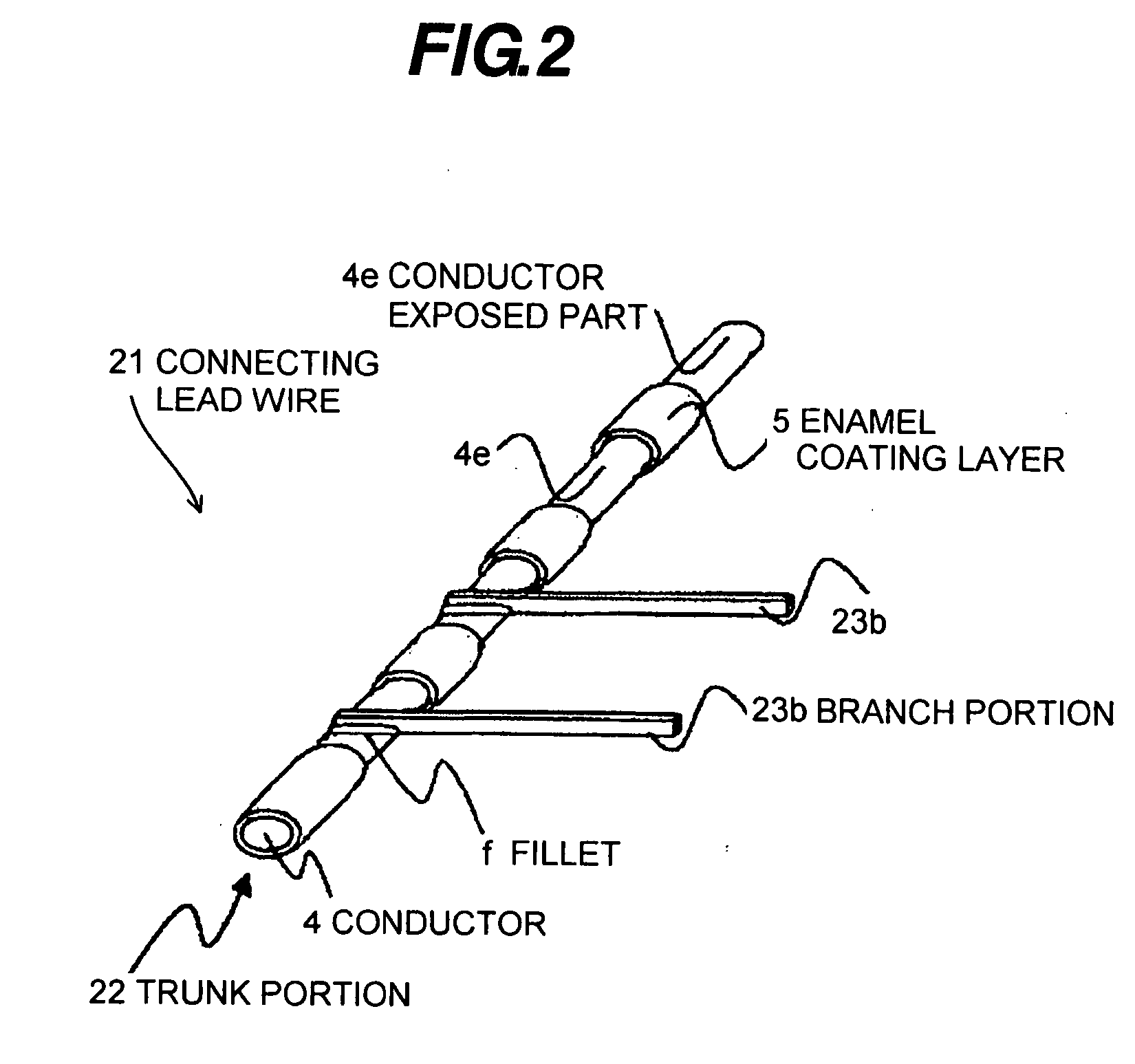
Corresponding to the Connecting Lead Wire 21 of FIG. 2

[0135] At first, a Cu-wire (center conductor) 4 having a conductor diameter of φ1.5 mm is prepared. Then, a brazing polyurethane enamel coating material is applied to the Cu-wire 4 and annealed repeatedly until a thickness of the brazing polyurethane enamel coating becomes 0.04 mm, so as to provide an enamel wire. An enamel coating layer 5 is removed in plural points at desired positions by mechanical method, and the enamel wire is cut with a length of 0.4 mm, to provide a segmented enamel wire (metal segmentation process).

[0136] On the other hand, two solder plated wires each having a rectangular cross section are prepared (branch portion 23b). The solder plated wire is fabricated by providing a solder plating layer (Sn—Pb fusion solder plating containing P of 0.01 mass %) on a Cu-wire.

[0137] As described above, the enamel coating layer 5 of the enamel wire to be used as a trunk portion 22 is removed at desired posit...

example 2

Corresponding to the Connecting Lead Wire 31 of FIG. 3, the Connecting Lead Wire 41 of FIG. 4, and the Connecting Lead Wire 61 of FIG. 6

[0140] At first, a Cu-wire (center conductor) 4 having a conductor diameter of φ1.5 mm is prepared. Then, a high melting point solder comprising Sn-3 wt % / Ag-0.5 wt % Cu and inevitable impurities is provided on the Cu-wire 4 by electrolysis electroplating method until a thickness of a solder plating layer 6 became 0.02 mm. Thereafter, a brazing polyurethane enamel coating material is applied to the high melting point solder plated Cu-wire 4 and annealed repeatedly, so as to provide an enamel wire. An enamel coating layer 5 is removed in plural points at desired positions by mechanical method, and the enamel wire is cut with a length of 0.4 m, to provide a segmented enamel wire (metal segmentation process).

[0141] On the other hand, two solder plated wires each having a rectangular cross section are prepared (second branch portions 33b, 43b, or 63b)....

example 3

Corresponding to the Connecting Lead Wire 51 of FIG. 5

[0147] At first, a Cu-wire (center conductor) 4 having a conductor diameter of φ1.5 mm is prepared. Then, a high melting point solder comprising Sn and inevitable impurities is provided on the Cu-wire 4 by electrolysis electroplating method until a thickness of a solder plating layer 6 becomes 0.01 mm. Thereafter, a brazing polyurethane enamel coating material is applied to the high melting point solder plated Cu-wire 4 and annealed repeatedly until a thickness of a brazing polyurethane enamel coating layer 5 becomes 0.04 mm, so as to provide an enamel wire. The enamel coating layer 5 is removed in plural points at desired positions by mechanical method, and the enamel wire is cut with a length of 0.4 mm, to provide a segmented enamel wire (metal segmentation process).

[0148] One enamel wire to be used as a trunk portion 52 in which the enamel coating layer 5 is removed at desired positions to expose the conductor 4 at predetermi...


PUM

PropertyMeasurementUnit
Percent by massaaaaaaaaaa
Currentaaaaaaaaaa

Abstract

A connecting lead wire is used for a solar battery module in which a plurality of solar battery cells connected in series by an inter-connector are arranged. The connecting lead wire is provided with a trunk portion and one or more branch portions. In the trunk portion, an enamel coating layer is provided on a conductor. In each of the branch portions, a solder plating layer is provided on a conductor. The branch portion protrudes from the trunk portion in a lateral direction, and connected to an electrode of each of the solar battery cells. The branch portion connects the solar battery cells with each other.

Description

[0001] The present application is based on Japanese Patent Application No. 2006-194708 filed on Jul. 14, 2006, the entire contents of which are incorporated herein by reference. BACKGROUND OF THE INVENTION [0002] 1. Field of the Invention [0003] The present invention relates to a connecting lead wire to be used in a solar battery module in which a plurality of solar battery cells are connected with a high density (a connecting lead wire for a solar battery), a method for fabricating the same, and a solar battery module using the connecting lead wire. [0004] 2. Related Art [0005] As shown in FIG. 13, a conventional solar battery module 120 in many cases comprises a solar battery cell column including a plurality of solar battery cells c connected in series or in parallel by using an inter-connector 121 for lateral connection or a bus-bar for vertical connection. Japanese Patent No. 3437027 discloses such a conventional solar battery module. [0006] As a connecting lead wire used in a ...

Claims


Application Information

Patent Timeline
IPC IPC(8): H01L31/05H01L31/02
CPCY02E10/50Y10T29/49355H01L31/0201
Inventor AOYAMA, SEIGITSUJI, TAKAYUKIOKIKAWA, HIROSHINISHI, HAJIME
Owner HITACHI CABLE
Learn More