
Vehicular Electrical System and Control Method Therefor

a technology of electrical system and vehicle, applied in the direction of battery/fuel cell control arrangement, vehicle sub-unit features, battery/cell propulsion, etc., can solve the problems of shortening the useful battery life, hev high power density battery will suffer battery longevity, hev high energy density battery, etc., to achieve rapid discharge and prevent draining

Active Publication Date: 2008-01-17
GM GLOBAL TECH OPERATIONS LLC
View PDF11 Cites 85 Cited by
  • Summary
  • Abstract
  • Description
  • Claims
  • Application Information

AI Technical Summary

Benefits of technology

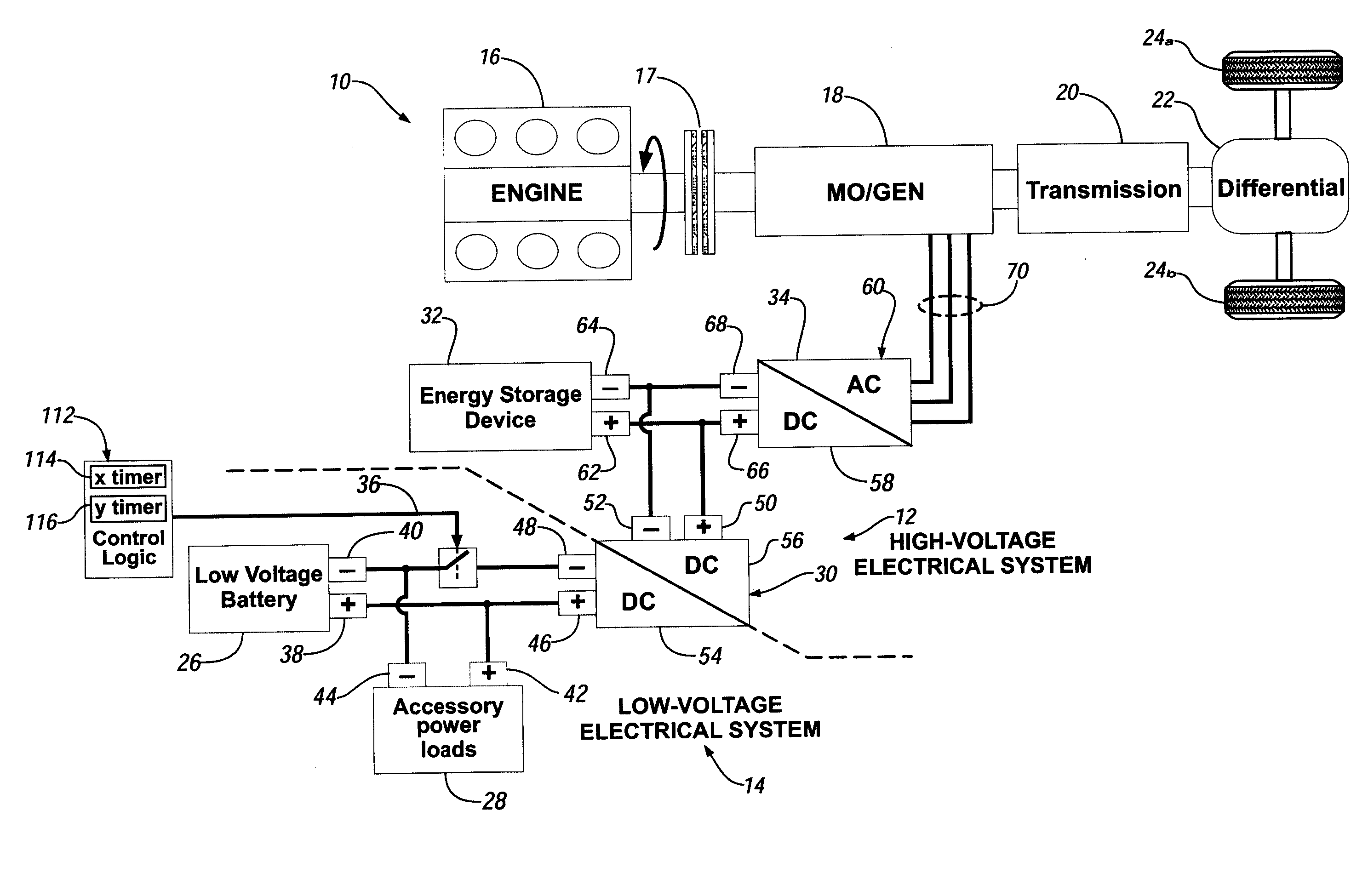
[0007]A vehicular electrical system and control method is provided for use in a HEV to prevent draining of a low voltage battery and rapid discharging of an associated high power electrical energy storage device (HPD). In accordance with one embodiment of the invention, a vehicular electrical system for a hybrid electric vehicle includes a high voltage electrical system having a...

Problems solved by technology

Consequently, deep discharges of batteries are not generally desirable as such tend to shorten useful battery life, and battery state of charge (SOC) is desirably maintained in a relatively narrow range toward an upper region thereof.
However, vehicle electrical accessory loads during engine off idle can be a substantial source of battery discharge.
Employing a high power density battery in HEV will suffer battery longevity.
Similarly, employing a high energy density battery will suffer HEV performance and operational flexibility.
While it is generally well recognized that high power electrical storage devices, such as supercapacitors, may provide many of the desired characteristics in a high voltage energy source for HEV, it is also well recognized that supercapacitors store far less energy than batteries and can be depleted rapidly when subjected to sustained electrical loads, which is an undesirable trait for vehicular use since periods of inactivity would result in unacceptable starting voltage states or accelerated discharge of vehicle batteries during such periods.

Method used


Image

  • Vehicular Electrical System and Control Method Therefor
  • Vehicular Electrical System and Control Method Therefor
  • Vehicular Electrical System and Control Method Therefor

Examples


Embodiment Construction

[0013]The invention is directed to a vehicular electrical system and control method for a HEV that provides an electrical energy storage device having a high power to energy ratio for use in combination with a DC to DC converter that interfaces a low voltage electrical system with a high voltage electrical system. A high power to energy ratio is defined as substantially a power to energy ratio (W / Whr, or 1 / hr) greater than 15 inverse hours. The HPD may be for example, a high voltage supercapacitor (SC) or an electrochemical storage device such as a lithium ion battery. Typically, a SC has an effective power to energy ratio of about 400 inverse hours. Additionally, a lithium ion battery typically has an effective power to energy ratio of about 20 inverse hours.

[0014]The vehicular electrical system and control method disclosed herein operates to reduce the draining of low voltage batteries during discharging of the high power electrical energy storage device.

[0015]More particularly, o...


PUM


Abstract

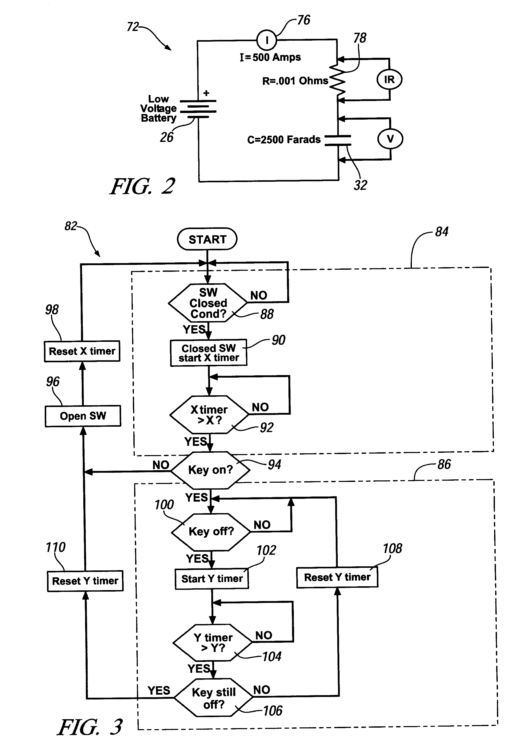
A vehicular electrical system for a hybrid electric vehicle provides a high voltage electrical system having a high power electrical energy storage device (HPD) and a power inverter that cooperate to provide power to a hybrid electric vehicle propulsion system; and a low voltage electrical system having a low voltage power source, at least one accessory power load, and a control switch that toggles between an opened and a closed position to control the flow of current flowing between the low voltage power source and the HPD. A method of using the vehicular electrical system provides the step of using the HPD and power inverter to provide power to the electric vehicle propulsion system; and opening a control switch to isolate the low voltage system from the high voltage system and closing a control switch to charge the HPD

Description

TECHNICAL FIELD[0001]The present invention is related to vehicular energy storage and retrieval. More particularly, the invention relates to electrical energy storage and retrieval in a hybrid electric vehicle.BACKGROUND OF THE INVENTION[0002]Battery-electric vehicles (BEV) and hybrid-electric vehicles (HEV) include one or more electric machines (propulsion motors) as part of a vehicle propulsion system. An HEV, in addition, includes a heat engine such as an internal combustion engine as part of the vehicle propulsion system. HEV may be generally categorized as strong or mild. Strong hybrids are characterized by high torque propulsion motors capable of imparting significant driveline torque contributions across a wide range of vehicle operating regions for traction and regenerative braking. Strong hybrids may further take form in series hybrid architecture, parallel hybrid architecture and series / parallel architectures. Mild hybrids are generally implemented in parallel hybrid archi...

Claims


Application Information

Patent Timeline
IPC IPC(8): B60K6/00
CPCB60K6/28Y10S903/904B60L11/123B60L11/1868B60L2240/28B60W10/06B60W10/08B60W10/26B60W20/00Y02T10/6217Y02T10/6221Y02T10/6278Y02T10/6286Y02T10/7011Y02T10/7022Y02T10/7066Y02T10/7077B60Y2400/112B60Y2400/114Y10S903/903Y10S903/907B60K6/48B60L50/61B60L58/20Y02T10/62Y02T10/70Y02T10/7072
Inventor VERBRUGGE, MARK W.TURNER, LANCE W.MITUTA, ANDRES V.
Owner GM GLOBAL TECH OPERATIONS LLC
Learn More