Imprint lithography

a technology of imprint lithography and lithography plate, which is applied in the field of imprint lithography, can solve the problems of difficult to achieve the effect of enhancing the resolution of the optical lithography machine, requiring complex optics and rare materials, and high cos

Active Publication Date: 2008-01-17
ASML NETHERLANDS BV +1
View PDF60 Cites 75 Cited by
  • Summary
  • Abstract
  • Description
  • Claims
  • Application Information

AI Technical Summary

Problems solved by technology

However, there are problems associated with such reductions.
Current systems are starting to adopt optical sources with wavelengths in the 193 nm regime but even at this level, diffraction limitations become a barrier.
At lower wavelengths, the transparency of materials is very poor.
Optical lithography machines capable of enhanced resolutions require complex optics and rare materials and are consequently very expensive.
The resolution of imprint lithography is largely limited only by the resolution of the template fabrication process.
This is an expensive and time consuming process.

Method used


Image

  • Imprint lithography
  • Imprint lithography
  • Imprint lithography

Examples


Embodiment Construction

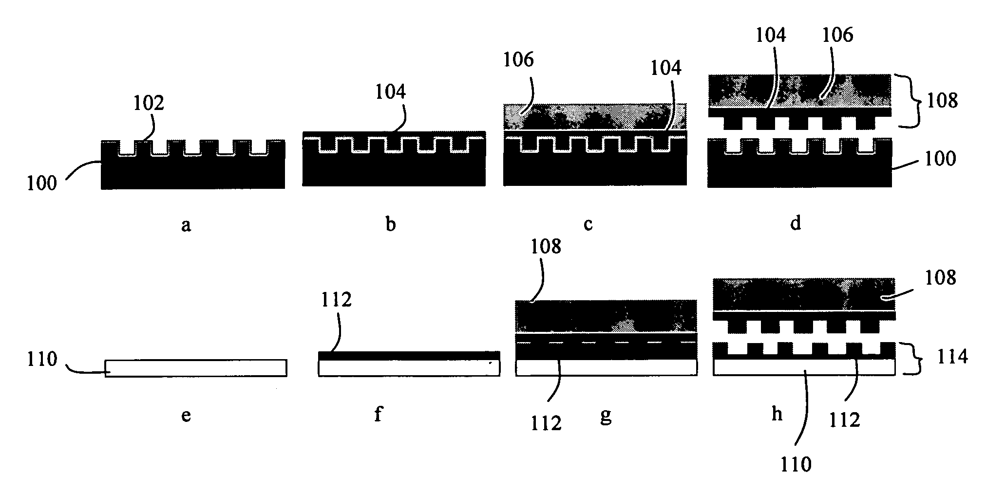
[0018]There are two principal approaches to imprint lithography which will be termed generally as hot imprint lithography and UV imprint lithography. There is also a third type of imprint lithography which may be referred to as “printing” lithography. Examples of these are illustrated in FIGS. 1a to 1c.

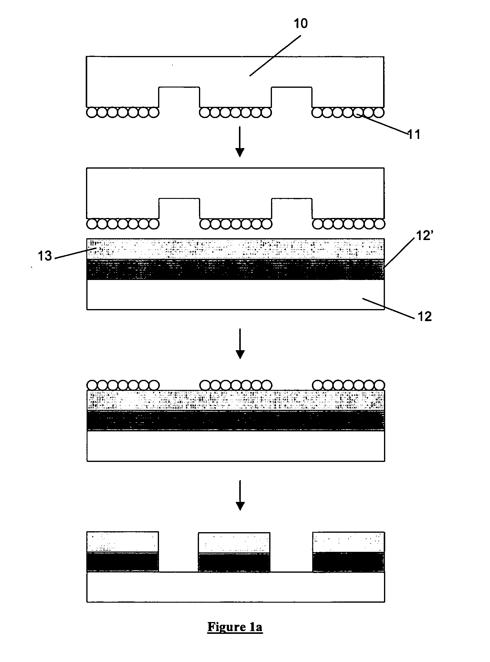
[0019]FIG. 1a shows a printing lithography process, known as micro-contact printing, which involves transferring a layer of molecules 11 (typically an ink such as a thiol) from a flexible template 10 (typically fabricated from polydimethylsiloxane (PDMS) onto a resist layer 13 which is supported upon a substrate 12 and planarisation and transfer layer 12′. The template 10 has a pattern of features on its surface, the molecular layer being disposed upon the features. When the template is pressed against the resist layer the layer of molecules 11 stick to the resist. Upon removal of the template from the resist the layer of molecules 11 stick to the resist, the residual layer of resist...


PUM

PropertyMeasurementUnit
wavelengthsaaaaaaaaaa
aspect ratioaaaaaaaaaa
thicknessaaaaaaaaaa

Abstract

A method of making an imprint lithography template includes applying a curable material to a patterned surface of a master imprint template, allowing the curable material to cure and thereby forming a second imprint template having a patterned surface which is the inverse of the patterned surface of the master imprint template; removing the second imprint template from the master imprint template; applying inorganic sol-gel to a substrate; imprinting the inorganic sol-gel with the second imprint template; allowing the inorganic sol-gel to cure; and removing the second imprint template from the cured inorganic sol-gel, such that the inorganic sol-gel forms a third imprint template having a patterned surface which corresponds with the patterned surface of the master imprint template.

Description

BACKGROUND OF THE INVENTION[0001]1. Field of the Invention[0002]The present invention relates to imprint lithography.[0003]2. Description of the Related Art[0004]A lithographic apparatus is a machine that applies a desired pattern onto a target portion of a substrate. Lithographic apparatus are conventionally used, for example, in the manufacture of integrated circuits (ICs), flat panel displays and other devices involving fine structures.[0005]It is desirable to reduce the size of features in a lithographic pattern because this allows for a greater density of features on a given substrate area. In photolithography, the increased resolution may be achieved by using light of shorter wavelength. However, there are problems associated with such reductions. Current systems are starting to adopt optical sources with wavelengths in the 193 nm regime but even at this level, diffraction limitations become a barrier. At lower wavelengths, the transparency of materials is very poor. Optical l...

Claims


Application Information

Patent Timeline
Patent Type & Authority Applications(United States)
IPC IPC(8): B28B7/34B29C33/40C04B33/32B29C33/58C23F1/00
CPCB29C33/3857B29C33/40B29C33/60G03F7/0002B29L2031/756B82Y10/00B82Y40/00B29K2083/00
Inventor VERSCHUUREN, MARCUS ANTONIUSWUISTER, SANDER FREDERIK
Owner ASML NETHERLANDS BV
Why Eureka
Try Eureka