Planar Motor Device, Stage Device, Exposure Device and Device Manufacturing Method

Inactive Publication Date: 2008-01-17
NIKON CORP
View PDF25 Cites 70 Cited by
  • Summary
  • Abstract
  • Description
  • Claims
  • Application Information

AI Technical Summary

Benefits of technology

[0014] According to the present invention, the magnetic flux generated by the coil is guided to the moving surface opposite to the magnets disposed in the moving part through the core member. Therefore, the magnets of the moving part can be downsized without reducing the thrust force to thereby reduce the weight of the moving part. Accordingly, the present invention has effects that the moving part can move at high acceleration and provide a high aligning accuracy. Moreover, the magnetic flux generated by the coil can be effectively used, which leads to an effect th

Problems solved by technology

Furthermore, life extension is required by avoiding mechanical friction to elongate the operation time of the exposure device by decreasing the maintenance opportunities.
In the above planar motor, however, the heating value increases when heavy current is applied to the coils and the heat generated by the coils causes, for example, a mechanical error due to expansion of members constituting the substrate stage, which results in deterioration of aligning accuracy.
On the other hand, upsizing the permanent magnets to increase the magnetic flux density increases the weight of the moving part.
The increa

Method used


Image

  • Planar Motor Device, Stage Device, Exposure Device and Device Manufacturing Method
  • Planar Motor Device, Stage Device, Exposure Device and Device Manufacturing Method
  • Planar Motor Device, Stage Device, Exposure Device and Device Manufacturing Method

Examples


Embodiment Construction

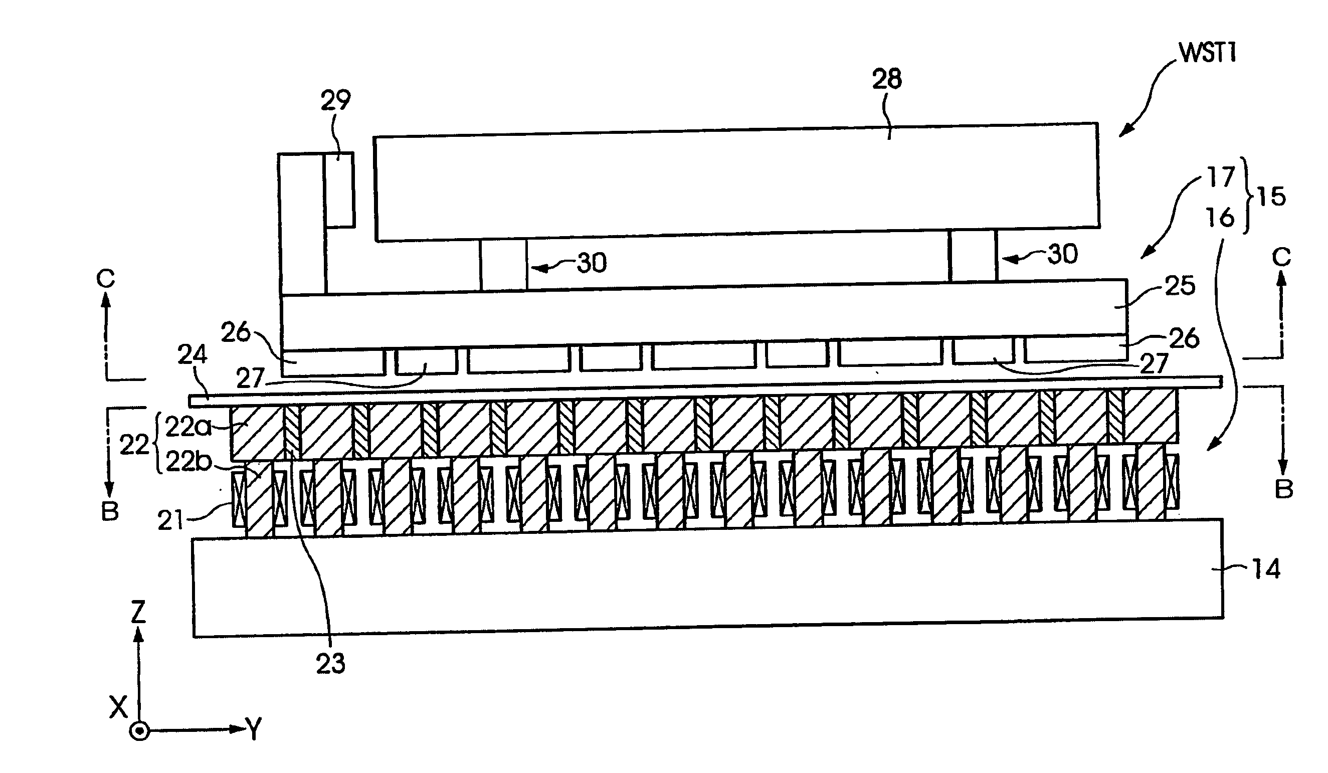
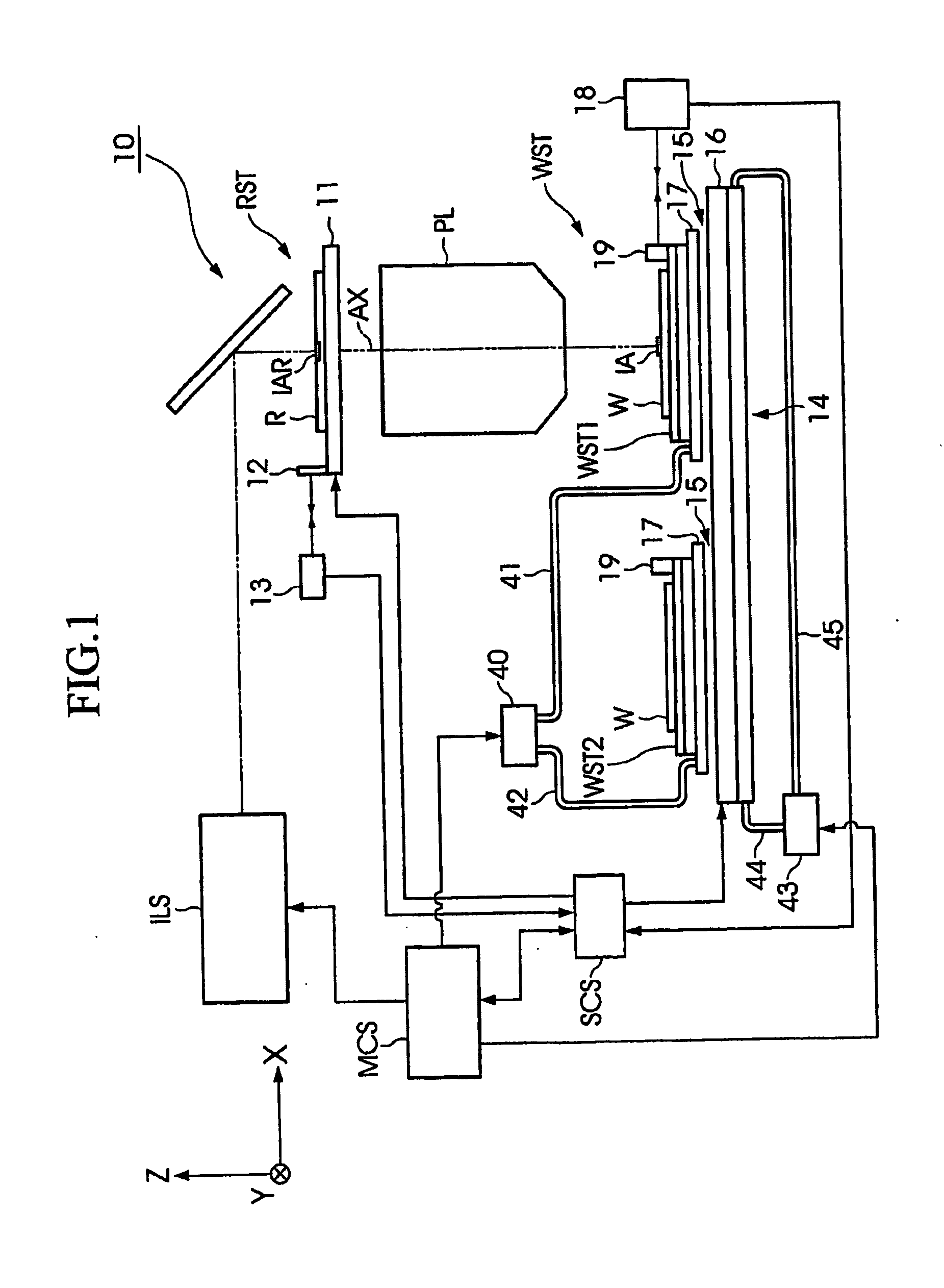
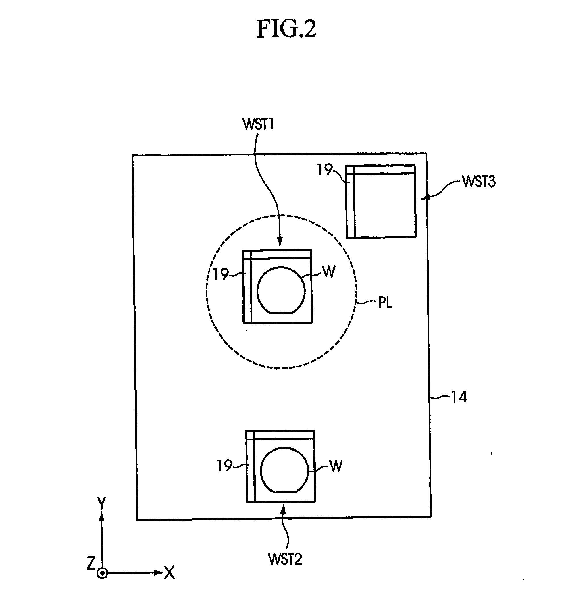
[0027] The following describes in detail planar motor device, stage device, and exposure device according to one embodiment of the present invention with reference to the drawings. Referring to FIG. 1, there is shown a diagram of a schematic configuration of the exposure device according to the embodiment of the present invention. The exposure device 10 shown in FIG. 1 is for use in manufacturing a semiconductor device and it is reduced projection type exposure device employing a step-and-scan system in which patterns formed on a reticle R are transferred sequentially onto a wafer W while the reticle R and the waver W are synchronously moved.

[0028] The following describes a positional relation between members with reference to an XYZ rectangular coordinate system with the XYZ rectangular coordinate system set in the drawings, if necessary. The XYZ rectangular coordinate system is set in such a way that the X axis and the Z axis are parallel to the paper surface and that the Y axis ...


PUM

PropertyMeasurementUnit
Flow rateaaaaaaaaaa
Accelerationaaaaaaaaaa
Thermal propertiesaaaaaaaaaa

Abstract

A planar motor device and the like which can shift at a high acceleration, provide a high aligning accuracy and can be efficiently driven is provided. The planar motor (15) includes a fixed part (16) provided on a base member (14), and a moving part (17) provided on a stage unit (WST1). The fixed part (16) is provided with core members (22), which are arranged at prescribed intervals within an XY plane with a coil (21) wound around, and leading edge parts of head parts (22a) of the core members (22) are set to be within a substantially one plane. On the bottom plane of a first stage (25) of the stage unit (WST1), permanent magnets (26) are arranged at prescribed intervals in an X direction and a Y direction.

Description

TECHNICAL FIELD [0001] The present invention relates to planar motor device which two-dimensionally drives a moving part with respect to a fixed part, stage device including the planar motor device as driving means, and exposure device including the stage device. [0002] This application claims priority to Japanese Patent Application No. 2004-208574, filed on Jul. 15, 2004, the contents of which are incorporated herein by reference. BACKGROUND ART [0003] In a photolithography process provided as one of the manufacturing processes for a semiconductor device, a liquid crystal display device, a charge coupled device (CCD) or other imaging devices, a thin film magnetic head, or other various devices, such exposure device is used that transfers a pattern formed on a mask or reticle (hereinafter, generally referred to as “mask”) through a projection optical system onto a substrate such as a glass plate or a wafer the surface of which is coated with a photoresist. In the exposure device, th...

Claims


Application Information

Patent Timeline
IPC IPC(8): H02K41/03
CPCG03F7/70758H02K41/031Y10T29/49117H02K1/146H02K1/278H02K2201/18
Inventor ONO, KAZUYA
Owner NIKON CORP
Why Eureka
Try Eureka