Hydrocarbon Tank Cleaning Systems

Inactive Publication Date: 2008-01-31
JR & JH HLDG
View PDF11 Cites 8 Cited by
  • Summary
  • Abstract
  • Description
  • Claims
  • Application Information

AI Technical Summary

Benefits of technology

[0034] Another cleaning technique can be to perform the cleaning operation as just described but to heat the re-circulating fluid using a heat exchanger such as exchanger 219. Heating can help soften the sludge by making it a partially-

Problems solved by technology

After these operations have gone as far as they can, a substantial amount of rust, scale and debris will typically be present on the tank.
This cannot be easily removed by the cutter stock method alone.
The problems associated with the Sludge Fluidization/Removal Method in general and the Cutter Stock technique in particular include: Inefficient and time consuming (up to 3 Months for 110 Meter Tank) Adds substantial volume, treatment time, cost and logistical transfer problems.
Heat Transfer is inefficient.
Heat loss results in re-solidification of sludge and creates pumping, circulation and solids separation difficulties.
Process safety concerns due to increased flammability and organic emissions.
Results in high volume of cutter stock that may require re-refining to remove dispersed sludge.
This method is time consuming, labor intensive and expensive.
The personnel working within the tank are exposed to potential health risks as well as possible injury.
Even when the previously discussed conventional methods are employed, the sludge is often not rendered sufficiently fluid by conventional methodology to be pumped out of the tank and at least some p

Method used


Image

  • Hydrocarbon Tank Cleaning Systems
  • Hydrocarbon Tank Cleaning Systems
  • Hydrocarbon Tank Cleaning Systems

Examples


Embodiment Construction

[0065] The numerous innovative teachings of the present application will be described with particular reference to the presently preferred embodiment (by was of example, and not of limitation).

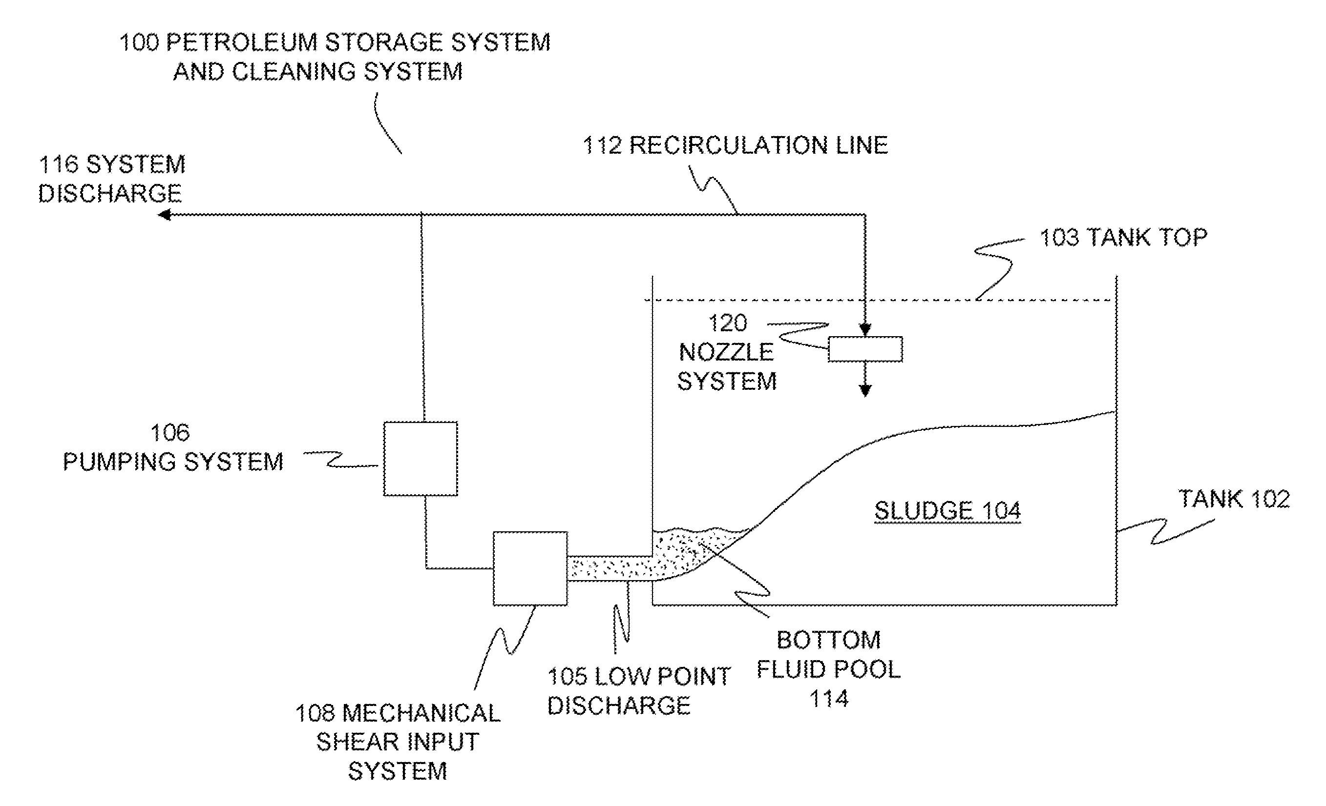
[0066]FIG. 1 shows one embodiment of a system of the present innovations. In this example, petroleum storage and cleaning system 100 comprises a tank 102 with sludge 104 on its interior surfaces (especially its bottom, as shown here). Tank 102 can be fitted with tank top 103. Fluid can be discharged from low point discharge 105. Mechanical shear input system 108 processes the stream from 105 to produce a flowable slurry.

[0067] The mechanical shear system 108 can be various types of comminution devices, as discussed below. System 108 feeds the input of pumping system 106, so that 108 and 106 are in a supercharging relationship which improves the suction lift over that which pump 106 could achieve alone.

[0068] The pumping system 106 raises the pressure of the fluid within recirculation line 1...


PUM


Abstract

Systems for cleaning sludge from a large tank. The sludge from the interior of storage tanks is mobilized using a metered flow agent stream and then subjected to a mechanical comminution or high shear action, e.g. by grinding or chopping. This produces a pumpable slurry which is then recirculated back into the tank to further mobilize sludge.

Description

CROSS-REFERENCE TO RELATED APPLICATIONS [0001] This application claims priority from U.S. Provisional Patent Applications 60 / 798,373 filed on May 5, 2006, entitled “Method of Processing and Removing Hydrocarbon Residues from a Tank”, of John C. Hancock, and 60 / 897,977 filed on Jan. 29, 2007, entitled “Hydrocarbon Tank Cleaning Methods and Systems”, also of John C. Hancock, which are both herein incorporated by reference in their entirety.BACKGROUND AND SUMMARY OF THE INVENTION [0002] The present disclosure is directed to cleaning methods and systems for hydrocarbon storage systems, and more particularly, but not by way of limitation, to petroleum oil storage tanks in which petroleum-based or other sludges have settled or precipitated on the surfaces of the tank as sludge. [0003] The following paragraphs contain some discussion which is illuminated by the innovations disclosed in this application, and any discussion of actual or proposed or possible approaches in these paragraphs doe...

Claims


Application Information

Patent Timeline
IPC IPC(8): B08B7/04B08B3/02B08B3/08B08B3/10
CPCB63B57/02B08B9/0933
Inventor HANCOCK, JOHN C.
Owner JR & JH HLDG
Why Eureka
Try Eureka