Chemical vapor deposition and powder formation using thermal spray

Inactive Publication Date: 2001-11-15
HUNT ANDREW T +1
View PDF0 Cites 22 Cited by
  • Summary
  • Abstract
  • Description
  • Claims
  • Application Information

AI Technical Summary

Problems solved by technology

However, for many materials there is a very limited selection of available precursors which can be vaporized and used for traditional CVD.
In addition, precursor vapor pressures do not play a role in CCVD because the dissolution process provides the energy for the creation of the necessary ionic constituents.
In general, the precursor materials used for traditional CVD depositions are between 10 and 1000 times more expensive than those which can be used in CCVD processing.
Finally, the CCVD technology generally uses halogen free chemical precursors having significantly reduced negative environmental impact compared to conventional CVD, resulting in more benign by-products.
Traditional CVD often requires months of effort to successfully deposit a material.
However, these atomization techniques cannot reach the highly desirable submicron capabilities which are important to obtaining improved coating and powder formation.
Additionally, no flame or plasma torch is used in this method, and only supercritical fluid solutions are considered.
All of the precursors of the '093 patent are carried in the supercritical solution which can limit the usable precursors due to reactivity and solubility in supercritical fluids.
Both Merkle et al. and McHale et al. deposited YBa.sub.2Cu.sub.3O.sub.x from a combusted sprayed solution onto substrates, but the deposition conditions resulted in low quality pyrolysis and particulate type coatings.
al. Even after oxygen annealing, zero resistivity could never be obtained at temperatures above 76.degree. K The solution concentrations used were not reported, but the deposition rates were excessively h
metry. Additionally the resulting droplet size of sprayed solutions was excessively large and the vapor pressure too low for effective vapor depo
The range of desired deposition distances from the plasma source was small due to the rapid temperature drop of the gases.
Many of these fluids are not stable as liquids at STP, and must be combined in a pressure cylinder or at a low temperature.
Conversely,

Method used


Image

  • Chemical vapor deposition and powder formation using thermal spray
  • Chemical vapor deposition and powder formation using thermal spray
  • Chemical vapor deposition and powder formation using thermal spray

Examples


example i

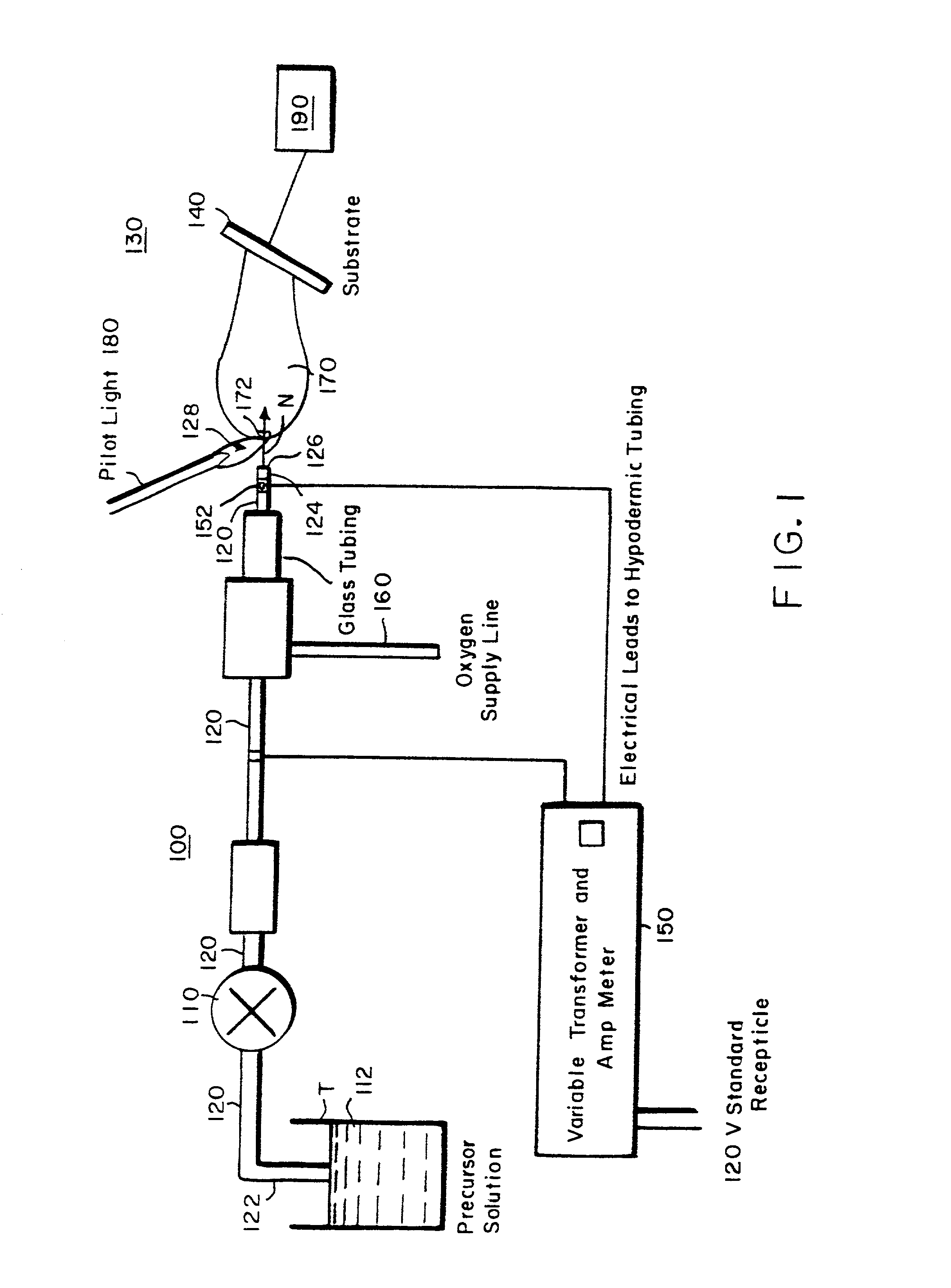
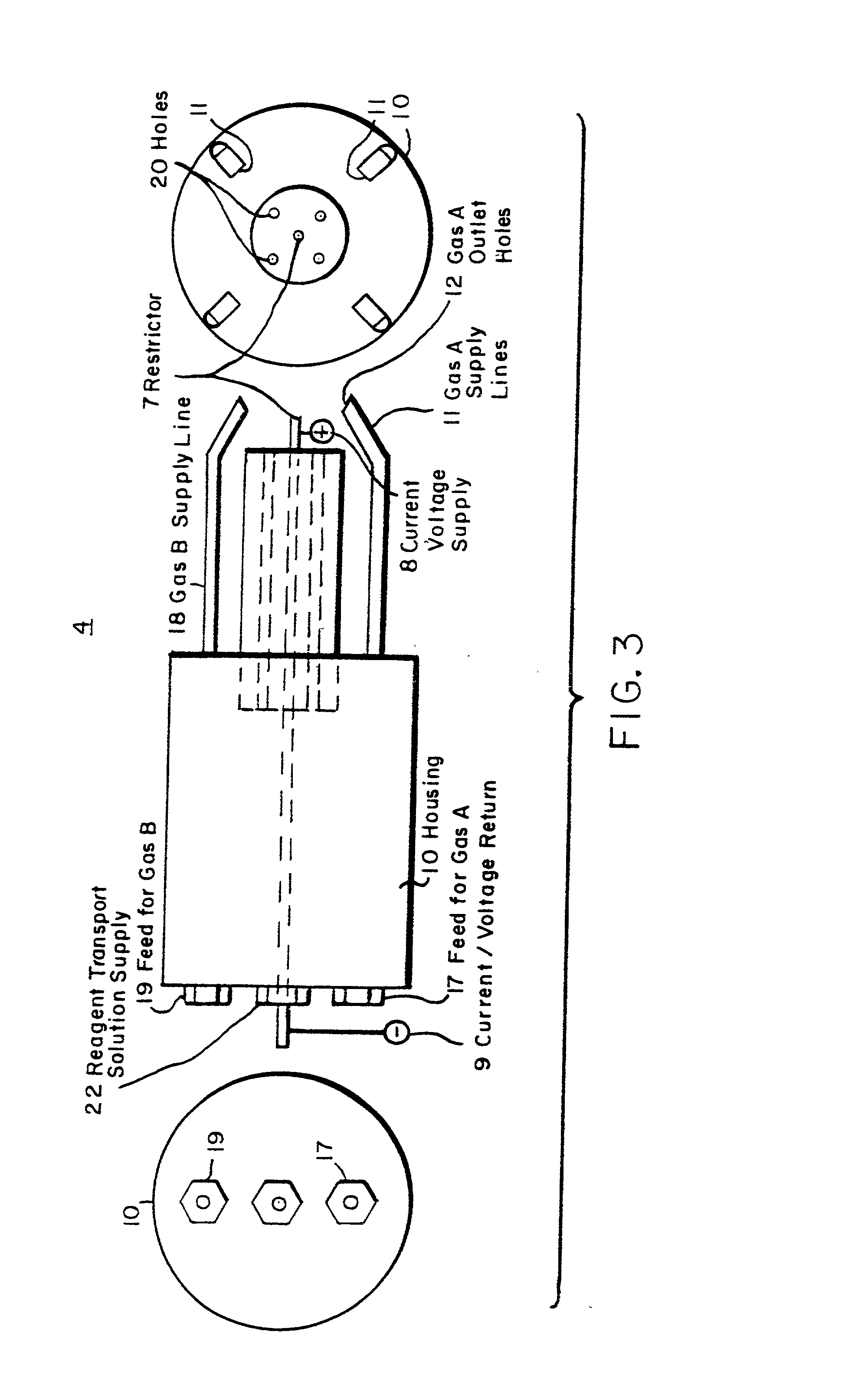
[0106] To illustrate the coating deposition capability of the process of the present invention, simple oxide coatings were formed on a metal substrate. SiO.sub.2 was deposited onto water cooled aluminum foil from a solution of tetraethoxysilane [Si(OC.sub.2H.sub.5).sub.4] dissolved in isopropanol to 2.1 wt % Si, additional isopropanol (3.2 ml) and propane (51 ml) were added for an overall silicon concentration of 0.06 M. The gas temperature for deposition was 1190.degree. C. The needle used to nebulize the precursor, as seen in FIG. 3, was 304 stainless steel with OD=0.012 inches and ID=0.004 inches. The resistance over the electrical flow length of the needle was about 1.6 W. Small pilot flames formed from combusted ethane and oxygen were used throughout the deposition to maintain the flame. The solution was pumped to the needle at 3 ml / min and nebulized by controlling the amount of current through the needle. In this example, the current was 2.65 A. The solution pressure from pump...

example ii

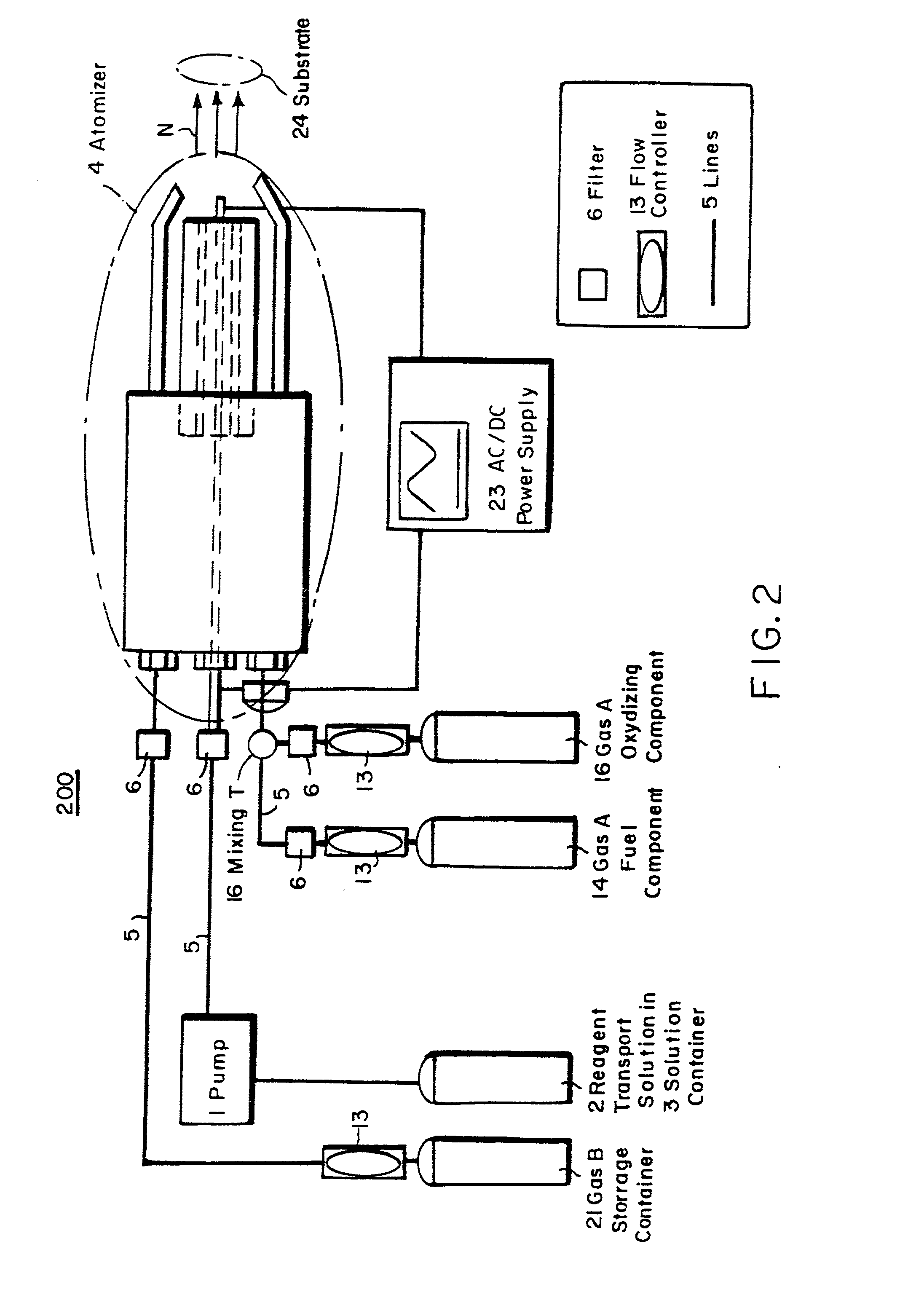
[0108] In addition to coatings formed on metal substrates, such as the oxide deposited on aluminum in Example I, coatings have also been formed on plastic substrates. Platinum was deposited onto Teflon at a gas temperature of 200 to 260.degree. C. from a 0.005M solution of platinum-acetylacetonate [Pt(CH.sub.3COCHCOCH.sub.3)..sub.2], toluene and methanol. The deposition apparatus used was similar to that used for Example I, except two separate pilot lights were used and the oxygen was supplied via a coaxial tube surrounding the reagent solution. The solution flow rate was 2 ml / min with a pressure of 1500 psi and a needle current of approximately 3.3 A. The oxygen flowed at a pressure of 20 psi and a rate of 4750 ml / min. The resulting adherent film was smooth, dense and uniform. X-ray diffraction ("XRD") confirmed the formation of platinum with a (111) preferred growth direction.

[0109] This example also illustrates that the coatings produced by the process of the present invention ar...

example iii

[0110] The coatings developed by the present invention are not limited to formation on planar substrates. Films have been deposited on ceramic fiber tows using the apparatus of the present invention. LaPO.sub.4 was deposited onto an alumina fiber tow from a solution of triethylphosphate [C.sub.2H..sub.5O.sub.3PO.sub.4] dissolved in toluene to 1.7 wt % P, lanthanum 2-ethylhexanoate dissolved in toluene to 1 wt % La, additional toluene (16 ml) and propane (273 ml). The resulting solution had concentrations of 0.0010M P and 0.0013M La. The solution flowed at a rate of 3 ml / min with a pressure of 410 psi during the deposition and was nebulized with a needle current of 2.36 A. The flow rate of oxygen to the solution flame was 4750 ml / min at a pressure of 30 psi.

[0111] The 400 fibers in the tow were coated at the same time. Each fiber was approximately 12 mm in diameter. The tow was slowly moved through the deposition zone of the flame two times. Only two passes through the flame (where t...


PUM

PropertyMeasurementUnit
Pressureaaaaaaaaaa
Energyaaaaaaaaaa

Abstract

A method for chemical vapor deposition using a very fine atomization or vaporization of a reagent containing liquid or liquid-like fluid near its supercritical temperature, where the resulting atomized or vaporized solution is entered into a flame or a plasma torch, and a powder is formed or a coating is deposited onto a substrate. The combustion flame can be stable from 10 torr to multiple atmospheres, and provides the energetic environment in which the reagent contained within the fluid can be reacted to form the desired powder or coating material on a substrate. The plasma torch likewise produces the required energy environment, but, unlike the flame, no oxidizer is needed so materials stable in only very low oxygen partial pressures can be formed. Using either the plasma torch or the combustion plasma, coatings can be deposited and powders formed in the open atmosphere without the necessity of a reaction chamber, but a chamber may be used for various reasons including process separation from the environment and pressure regulation.

Description

I. RELATED CASES[0001] This application is a division of U.S. patent application Ser. No. 09 / 293,867 filed Apr. 16, 1999, which is a divisional of U.S. patent application Ser. No. 08 / 691,853, filed Aug. 2, 1996, now U.S. Pat. No. 5,997,956, which claims the benefit of U.S. Provisional Application Ser. No. 60 / 002,084, filed Aug. 4, 1995, the contents of which are hereby incorporated in their entirety by this reference.II. FIELD OF THE INVENTION[0002] This invention relates to methods of powder formation and thin film deposition from reagents contained in liquid or liquid-like fluid solutions, whereby the fluid solution, near its supercritical point temperature, is released into a region of lower pressure causing a superior, very fine atomization or vaporization of the solution. Gasses are entrained or fed into the dispersed solution and rapidly flow into a flame or plasma torch. The reagents react and form either: 1) powders which are collected; or 2) a coating from the vapor phase o...

Claims


Application Information

Patent Timeline
IPC IPC(8): B05D1/02H05H1/24B22F9/28C01B13/34C23C16/44C23C16/448C23C16/453
CPCB22F9/28C01B13/34C23C16/4486C23C16/453Y10T428/265B05D1/08B05D2401/90Y10T428/25Y10T428/256Y02T50/67Y02P20/54Y02T50/60
Inventor HUNT, ANDREW T.HORNIS, HELMUT G.
Owner HUNT ANDREW T
Why Eureka
Try Eureka