
Chemical Analysis Using Dynamic Viscometry

a dynamic viscometry and chemical analysis technology, applied in the direction of biochemistry apparatus, biochemistry apparatus and processes, material testing goods, etc., can solve the problems of inability to examine small reaction volumes, high cost of methods, and inability to monitor the progress of reaction fluorescence, so as to achieve reproducible measurements and stable results, and without impairing the high frequency stability of the phase control loop

Inactive Publication Date: 2008-01-31
DUAL JURG +2
View PDF9 Cites 7 Cited by
  • Summary
  • Abstract
  • Description
  • Claims
  • Application Information

AI Technical Summary

Benefits of technology

[0016]The method of the invention makes it possible in particular to carry out very cost-effectively methods for screening for the presence of nucleic acids of particular organisms or for the presence of a mutation in the genetic material of an organism, especially of a microbial, plant or animal (including human) organism. For the last-mentioned application, the method preferably includes further analysis steps which allow the presence of a mutation in a nucleic acid to be determined.
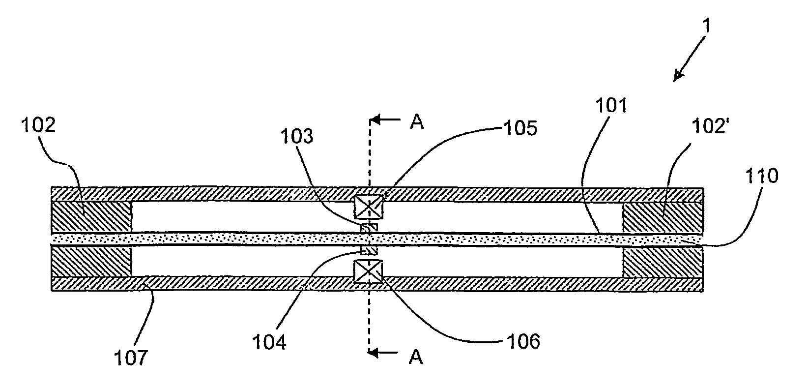
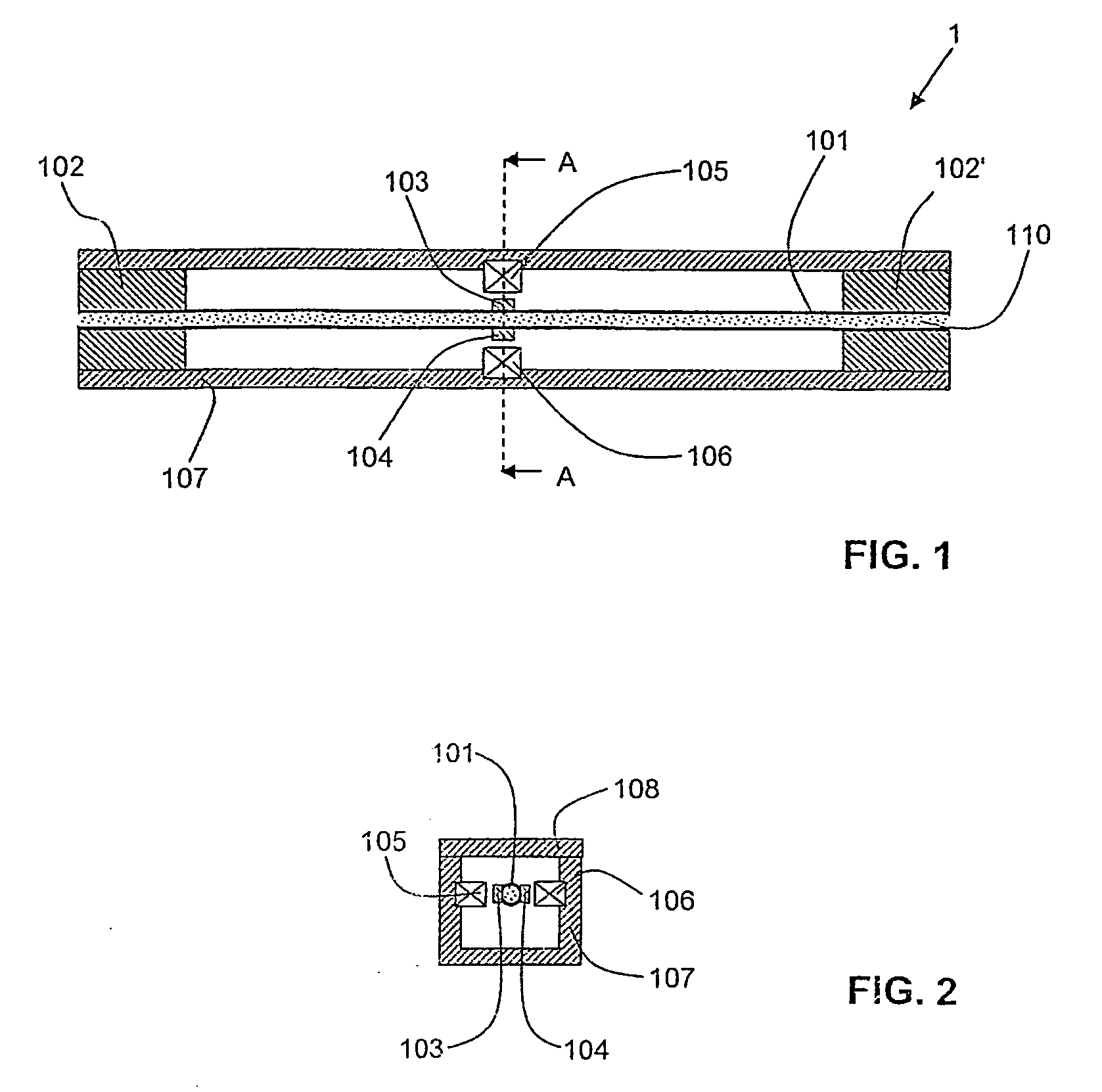
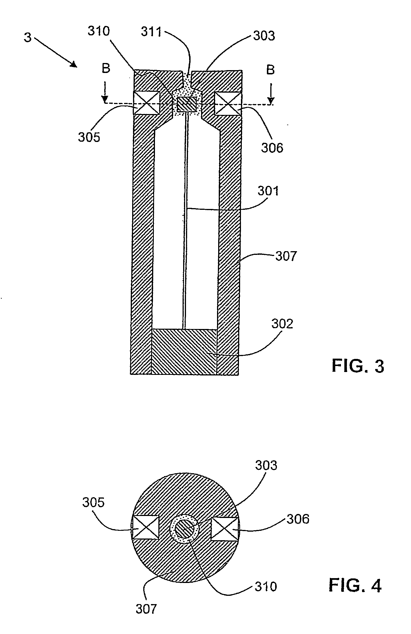
[0038]The viscometer is preferably operated with a phase control loop as described in detail in U.S. Pat. No. 4,920,787 or WO 95 / 24630. For this purpose, the apparatus has a feedback unit which comprises an oscillator driving the first transducer. The feedback unit is intended to stabilize the resonator in the region of a characteristic frequency. For this purpose, an output terminal of the feedback unit is connected at least indirectly to the first transducer which stimulates the resonator to vibrations. The same transducer serves likewise to detect the vibrations, or a second transducer is present for this purpose on the resonator. An input terminal of the feedback device is connected at least indirectly to the first transducer or the second transducer. Operation with such a control loop makes particularly stable, reproducible measurements possible.

Problems solved by technology

Monitoring the progress of a reaction by fluorescence is relatively complicated, because a sensitive optical system must be provided for detection.
In addition, such a method is costly to use because of the fluorescence markers necessary therefor.
The viscometers employed for this purpose are, however, ordinarily optimized for industrial production plants and unsuitable for examining small reaction volumes.

Method used


Image

  • Chemical Analysis Using Dynamic Viscometry
  • Chemical Analysis Using Dynamic Viscometry
  • Chemical Analysis Using Dynamic Viscometry

Examples


example

[0096]Detection of the “Factor V Leiden” Mutation

[0097]The factor V Leiden mutation is a single point mutation (G instead of A) in the human gene sequence, leading to a glutamine residue being replaced by an arginine residue at position 506 in the protein (a clotting factor) encoded by the sequence. Further information on this mutation is to be found for example in R. M. Bertina et al., “Mutation in Blood Coagulation Factor V Associated with Resistance to Activated Protein C”, Nature 369, 64-67 (1994). The entire nucleotide sequence of the factor V gene is described in: R. J. Jenny et al., “Complete cDNA and Derived Amino Acid Sequence of Human Factor V”, Proc. Nat. Acad. USA 84, 4846-4850 (1987). The risk of thrombosis is markedly increased in individuals having the mutation compared with individuals of the wild type, which is, why this mutation is the subject of a laboratory test which is frequently carried out in clinical genetics laboratories.

[0098]In the method normally carried...


PUM

PropertyMeasurementUnit
Diameteraaaaaaaaaa
Volumeaaaaaaaaaa
Temperatureaaaaaaaaaa

Abstract

The invention relates to a method for determining the reactive state of a chemical reaction process in a reaction mixture (110), in particular an amplification reaction for nucleic acids. Said method comprises a viscosity determination, which preferably uses a dynamic viscometer (1). The invention also relates to an improved dynamic viscometer (1) for carrying out said method. Said viscometer is characterised by an appropriate choice of material for the resonator (101) and optimised geometric ratios.

Description

TECHNICAL FIELD[0001]The present invention relates to a method and an apparatus for determining the reaction status of a chemical reaction, in particular a reaction for amplifying nucleic acids.PRIOR ART / BACKGROUND OF THE INVENTION [0002]It is usually desired in chemical reactions to quantify the result of the reaction by measuring suitable variables or to follow the progress of the reaction by means of such a variable. A well-known example is following the changes in color of a colored indicator which has been added to a reaction mixture.[0003]In a process for amplifying nucleic acids, in contrast to usual chemical reactions, a precursor is not converted into a completely different product, but one part of a molecule is copied with the aid of other precursors. In the specific case of methods for amplifying nucleic acids, especially the polymerase chain reaction (PCR), the result of the reaction is nowadays frequently quantified by staining with ethidium bromide and detecting the fl...

Claims


Application Information

Patent Timeline
IPC IPC(8): C12Q1/68B01J19/00G01N33/00C12M1/34G01N11/16
CPCC12Q1/6816G01N11/162Y10T436/145555C12Q2527/137
Inventor DUAL, JURGBESTMANN, LUKASHAUSLER, KLAUS
Owner DUAL JURG
Learn More