Method for evaluating the fatigue strength of welded joints

a fatigue strength and joint technology, applied in the field of welding, can solve the problems of welded joint damage, metal melting or diffuse, and original defects of parts,

Active Publication Date: 2008-02-07
SN DETUDE & DE CONSTR DE MOTEURS DAVIATION S N E C M A
View PDF8 Cites 14 Cited by
  • Summary
  • Abstract
  • Description
  • Claims
  • Application Information

AI Technical Summary

Benefits of technology

[0031]The benefit of the method lies in the fact that these blowholes are not detectable by standard methods and that this approach makes it possible to take into account defects that are much smaller than those given by the detection threshold of the usual nondestructive methods. This approach therefore justifies longer lifetimes than those that take the detectability thresholds into account.
[0032]From the det

Problems solved by technology

In particular, the parts may be joined by supplying heat, causing the metal to melt or diffuse.
This fatigue stressing may result prematurely in destruction of the welded joints.
In the majority of cases, postmortem fractographic analyses show that the parts originally had defects

Method used


Image

  • Method for evaluating the fatigue strength of welded joints
  • Method for evaluating the fatigue strength of welded joints
  • Method for evaluating the fatigue strength of welded joints

Examples


Embodiment Construction

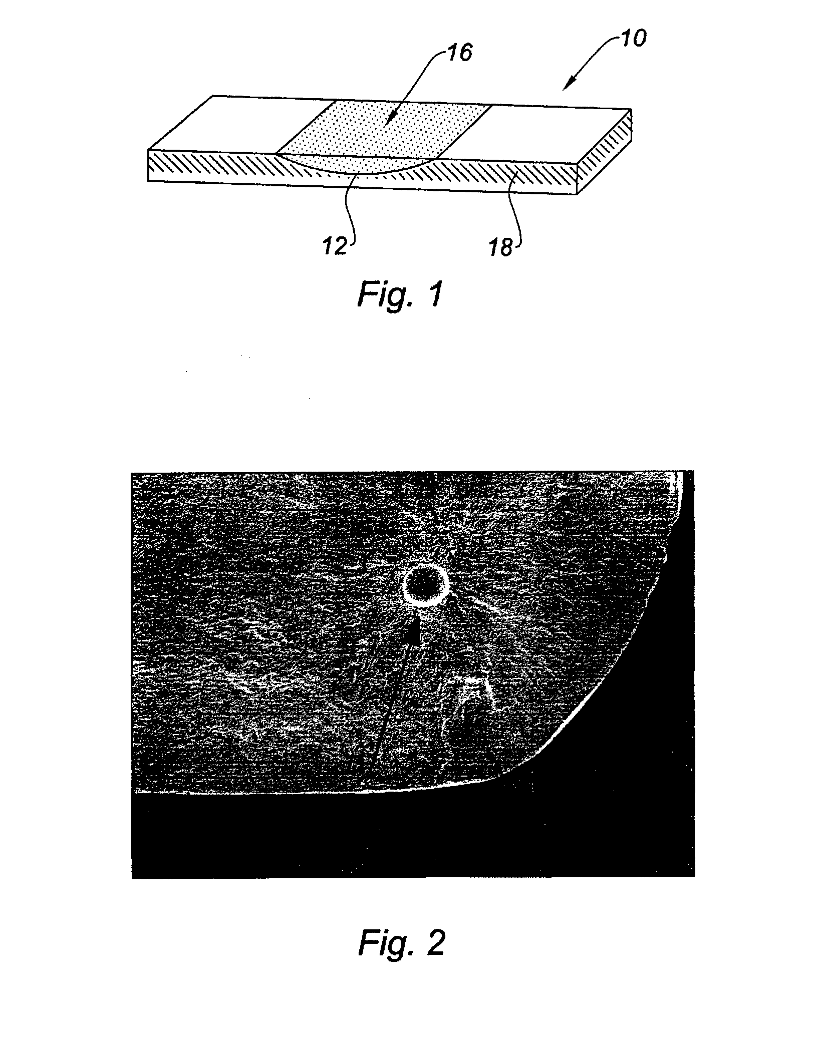
[0038]The specimens are produced for example using the following method. A cavity 12 is machined in a metal plate 10 of parallelepipedal shape and this cavity is filled with the alloy in question so as to form a welded joint 16. For the tests, resurfacing with TA6V alloy was carried out on Ti17 alloy plates.

[0039]The resurfacing operation is carried out using the same welding technique as that used for repairing the intended industrial parts. The same equipment is employed with the same welding parameters. The invention generally applies to welding modes that are fully controlled and can be defined by significant parameters. For deposition of metal with heating by means of a laser beam, the parameters are in particular those that characterize the beam, namely type, wavelength, focal length, beam homogeneity, energy density, distance to the target, shielding of the molten pool, etc.

[0040]The benefit of controlling the process stems from the observation whereby, upon solidifying, the ...


PUM

PropertyMeasurementUnit
Fractionaaaaaaaaaa
Fractionaaaaaaaaaa
Fractionaaaaaaaaaa

Abstract

Method for evaluating the fatigue strength of welded joints produced by melting an alloy using a specified welding technique, which method comprises the following steps:
a statistically significant number N of specimens are produced with a welded joint using said welding technique;
each of the specimens is subjected to cyclic fatigue tests, with an alternating stress a, until failure;
the size of the relevant defect appearing in the fracture plane of the specimens is measured by fractography;
a range of defect dimensions for which the probability of measuring by fractography a defect outside the range is less than a predetermined level of probability t is determined from the measured sizes; and
the lowest stress σmin liable to cause the specimen to fail with a level of probability t is determined from this range.

Description

BACKGROUND OF THE INVENTION [0001]The present invention relates to the field of welding.DESCRIPTION OF THE PRIOR ART [0002]There are various methods for joining two metal parts together. In particular, the parts may be joined by supplying heat, causing the metal to melt or diffuse. TIG, plasma, laser or inertia friction welding techniques are for example known. Moreover, missing metal on a part, for example resulting from wear, may be repaired by material resurfacing by means of a molten metal. In this case too, TIG, plasma, microplasma or other welding techniques are employed.[0003]When considering the field of turbomachines, the metal parts thus resurfaced or joined may often be subjected to cyclically repeated vibrations, stresses or strains. This fatigue stressing may result prematurely in destruction of the welded joints.[0004]In the majority of cases, postmortem fractographic analyses show that the parts originally had defects that initiated fatigue cracks. These are small def...

Claims


Application Information

Patent Timeline
IPC IPC(8): G01N3/32
CPCB23K26/34B23K31/12B23K2203/14G01N3/00B23K26/322G01N2203/0066G01N2203/0067G01N2203/0073G01N2203/0005B23K26/32B23K2103/14
Inventor MONS, CLAUDE MARCEL
Owner SN DETUDE & DE CONSTR DE MOTEURS DAVIATION S N E C M A
Why Eureka
Try Eureka