Eureka AIR delivers breakthrough ideas for toughest innovation challenges, trusted by R&D personnel around the world.

Anti-Reflective Coating for a Substrate

Inactive Publication Date: 2008-02-07
TRU VUE
View PDF11 Cites 30 Cited by
  • Summary
  • Abstract
  • Description
  • Claims
  • Application Information

AI Technical Summary

Benefits of technology

[0014] In general, the present invention relates to an anti-reflective coating for a substrate which is cost effective, which facilitates easy cleaning of the anti-reflective coating which has minimal, if any, effect on the optical performance of the coated substrate and which also exhibits improved anti-static properties. The invention also relates to a method of applying an anti-reflective coating to a substrate.
[0015] In accordance with the present invention, the anti-reflective coating includes a conventional anti-reflective stack applied to the substrate and a thin metal oxide layer applied to the outer surface of the anti-reflective stack. The metal oxides that are usable in the present invention are metal oxides which exhibit a refractive index greater than that of the underlying substrate. This will normally be about 1.52 or more. More preferably, this metal oxide layer has a refractive index greater than 1.6 and most preferably, a refractive index greater than 1.7. Examples of metal oxides which can serve as this outer layer include titanium dioxide (TiO2), zirconium dioxide (ZrO2), yttrium oxide (Y2O3), niobium oxide (Nb2O5), hafnium dioxide (HfO2), cerium dioxide (CeO2), tin dioxide (SnO2) and aluminum oxide (Al2O3), among others. It is believed that these metal oxides react to some extent with atmospheric carbon or other sources of carbon to form C—H bonds on the metal oxide surface. The existence of these C—H bonds tends to reduce the surface energy of that surface and thus facilitate easy cleaning of the coated substrate.
[0016] To minimize any adverse effect of the metal oxide layer on the optical performance of the underlying anti-reflective stack, the metal oxide layer should be as thin as possible, while still being thick enough to form a continuous film over the outer surface of the anti-reflective stack. Such continuous film provides sites for C—H bonding with atmospheric carbon or other carbon sources over the entire surface. Most preferably, the metal oxide layer should be less than about 10 nanometers thick.

Problems solved by technology

A drawback of anti-reflection coatings, and in particular optical interference anti-reflective coatings, is that they readily show fingerprints and are more difficult to clean than the corresponding uncoated substrate.
As is generally recognized in the art, a high index material or film (such as a fingerprint), on top of an anti-reflective coating will tend to destroy the anti-reflective nature of the coating, thereby making the fingerprint much more visible.
A substrate coated with an anti-reflective film is also more difficult to clean because the anti-reflective film typically has a higher surface energy than the uncoated substrate, thereby resulting in the contamination clinging more tenaciously to the surface.
While many of the currently available anti-soiling or other coatings and treatments for anti-reflective coatings are generally acceptable in that they facilitate the cleaning of anti-reflective coated substrates, they tend to be quite expensive, both in terms of materials and the labor for application.
Further, because many anti-reflective coatings as well as the substrates on which they are applied are employed and selected for their optical properties such as light transmission, color, ability to reduce reflection, etc., and because the application of any additional coating on an anti-reflective coating may adversely affect one or more of these desired optical properties, any such additional coating must be carefully selected.

Method used


Image

  • Anti-Reflective Coating for a Substrate
  • Anti-Reflective Coating for a Substrate

Examples


Embodiment Construction

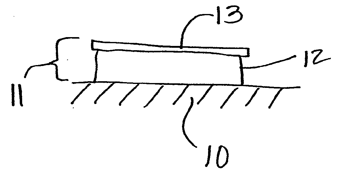
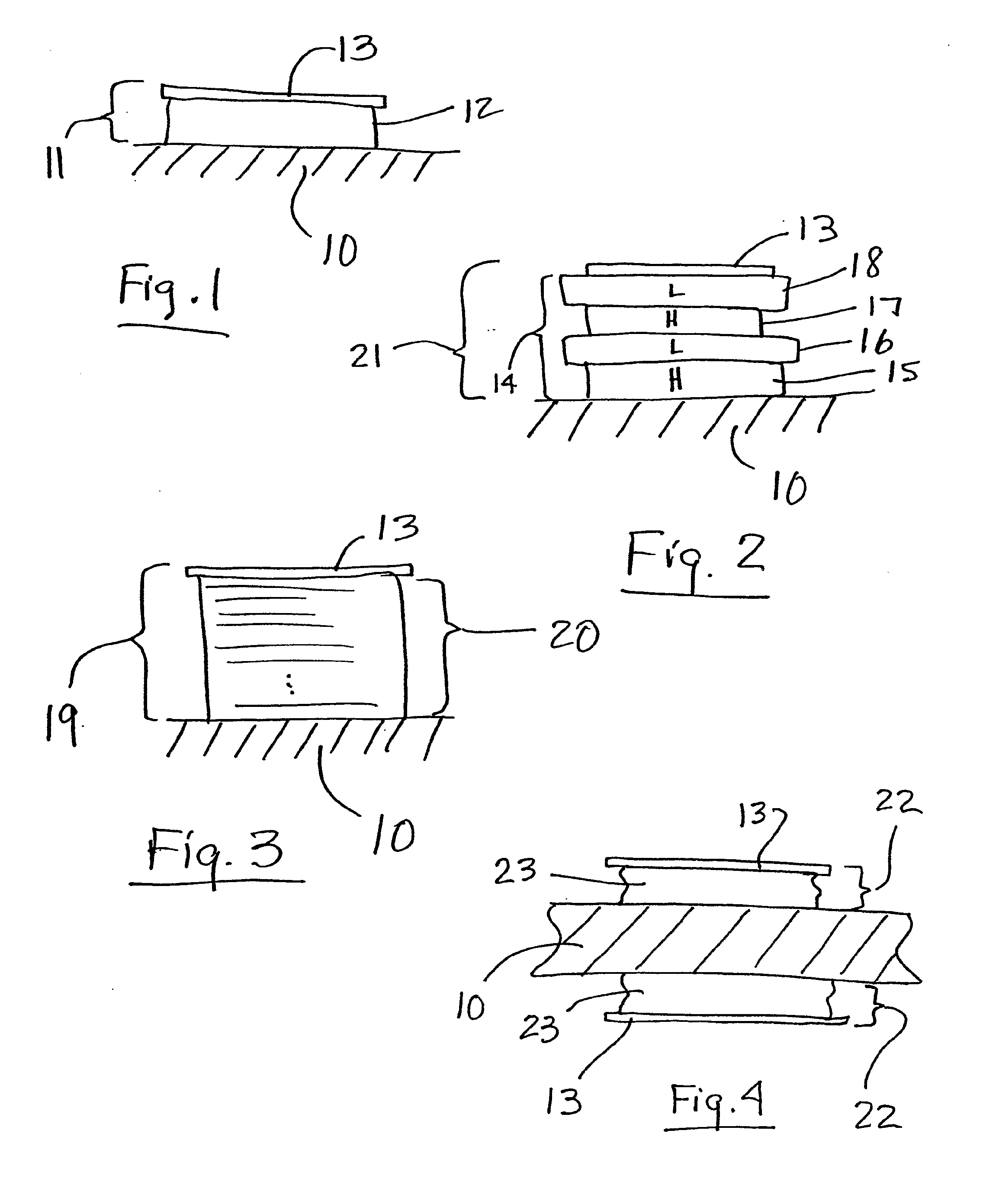
[0031] The present invention relates generally to an anti-reflective coating for a substrate and a method of applying an anti-reflective coating to a substrate. The anti-reflective coating in accordance with the invention includes an anti-reflective stack applied to a substrate and a thin high refractive index metal oxide coating applied to the outer surface of the anti-reflective stack. The preferred method in accordance with the present invention includes providing a substrate to be coated, applying an anti-reflective stack to the substrate and applying a thin, high refractive index metal oxide layer to the outer surface of the anti-reflective stack. The invention further contemplates and includes the provision of an anti-reflective stack in which the desired optical properties have been re-optimized to compensate for the added metal oxide layer.

[0032] The substrate to which the anti-reflective coating is applied in accordance with the present invention may include any transparen...


PUM

PropertyMeasurementUnit
Thicknessaaaaaaaaaa
Nanoscale particle sizeaaaaaaaaaa
Refractive indexaaaaaaaaaa

Abstract

An anti-reflective coating for a substrate which includes an outer metal oxide layer with a refractive index greater than the refractive index of the substrate. The invention also relates to a method for making the anti-reflection coating.

Description

BACKGROUND OF THE INVENTION [0001] 1. Field of the Invention [0002] The present invention relates to an anti-reflective coating for a substrate and more particularly to an anti-reflective coating that can be readily and easily cleaned and exhibit anti-static properties. The invention also relates to a method of making and applying the anti-reflective coating to a substrate. [0003] 2. Description of the Prior Art [0004] Anti-reflective coatings are applied to transparent, substantially transparent and light submissive substrates for the purpose of reducing glare and reflection from the substrate surface. A major application of anti-reflective coatings is in the display industry comprised of televisions, computer monitors, cathode ray tubes (CRTs), flat panel displays, and display filters for the above, among others. Anti-reflective coatings have been a great benefit to the display industry in that such coatings have made the displays easier and more pleasant to view and have helped t...

Claims


Application Information

Patent Timeline
IPC IPC(8): B32B17/00G02B1/11C03C17/34
CPCC03C17/34G02B1/115C03C17/3417
Inventor MEREDITH, WILLIAM A.ANDERSON, JOEL T.GERMAN, JOHN R.WOODRUFF, DANIEL P.
Owner TRU VUE
Why Eureka
Eureka Blog
Learn More