[0012] The object of the invention can be achieved by providing an apparatus characterized in that the container is designed such, that the tilting moment of the container caused by a
buoyancy of the container, the
buoyancy being a result of a liquid level differential, exceeds a frictional moment independent of the orientation of the container, the frictional moment being a result of the mutual cooperation of the container and the discharge means. By retaining a relatively high tilting moment with respect to the frictional moment in any orientation of the container, the container is given (under normal operating conditions) a permanent self-adjusting capacity. In this manner, jamming of the container and hence loss of the self-adjusting capacity due to a relatively high degree of friction with respect to the driving force can be prevented. Even in situations with relatively low liquid levels, the tilting moment, preferably largely, exceeds the frictional moment of the apparatus. To secure a permanent self-adjusting capacity of the tiltable container, the center of
buoyancy of the container, and eventually a part of the body of liquid, is preferably positioned at a (large) distance of the rotatable connection of the container and the discharge means.
[0013] To optimize the degree of freedom of design of the container, it is advantageous that the apparatus further comprises a feeding inlet coupled to said container for skimming the top layer of said body of liquid and feeding the container with the skimmed top layer. In this manner, both the container and the feeding inlet can be designed in an optimal way to realize the permanent self-adjusting capacity of the container, and in particular of the
assembly of the container and the feeding inlet. Said feeding inlet preferably comprises a skimming mouth, wherein said mouth is positioned at a distance of the container. By positioning the skimming mouth at a distance of the container, the design of the container and the feeding inlet can further be optimized. Besides a permanent self-adjusting capacity of the apparatus, a further
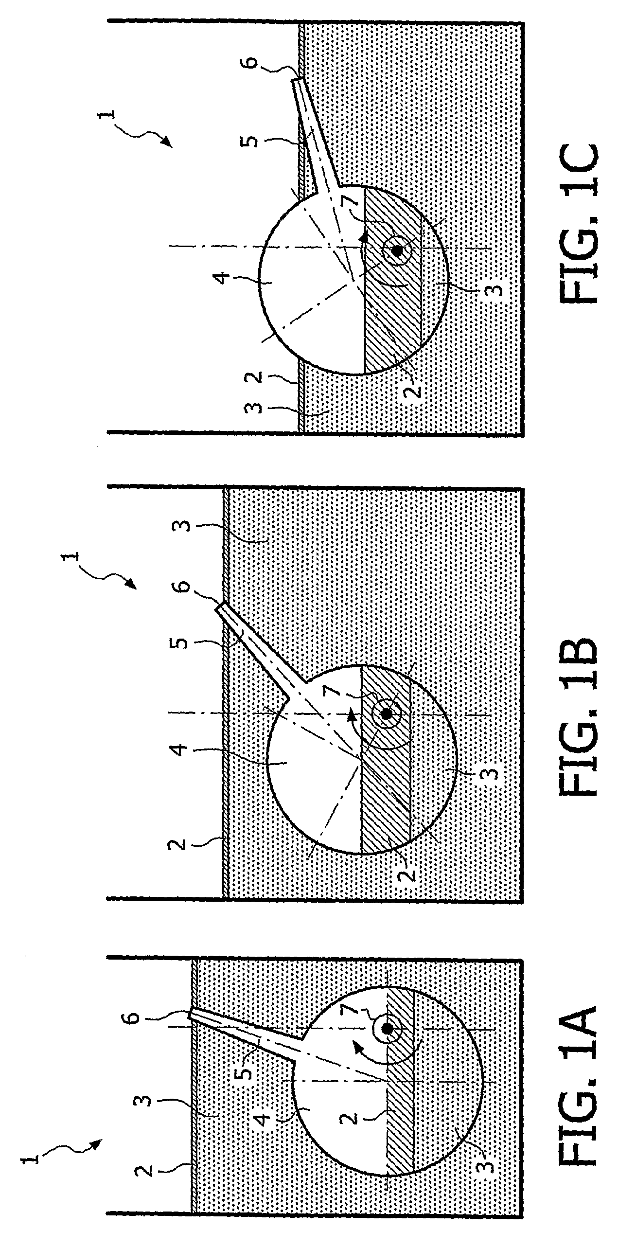
advantage of the apparatus is that the apparatus, in particular the skimming mouth, can be tilted over a relatively
large distance with respect to the displacement of the skimming mouth of a conventional skimming apparatus having an identical internal collecting and storage volume. In particular the
vertical displacement of the skimming mouth can be increased significantly, as a result of which the apparatus according to the invention is adapted to function in a normal manner in a relatively broad range of liquid levels.
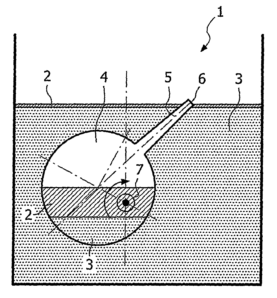
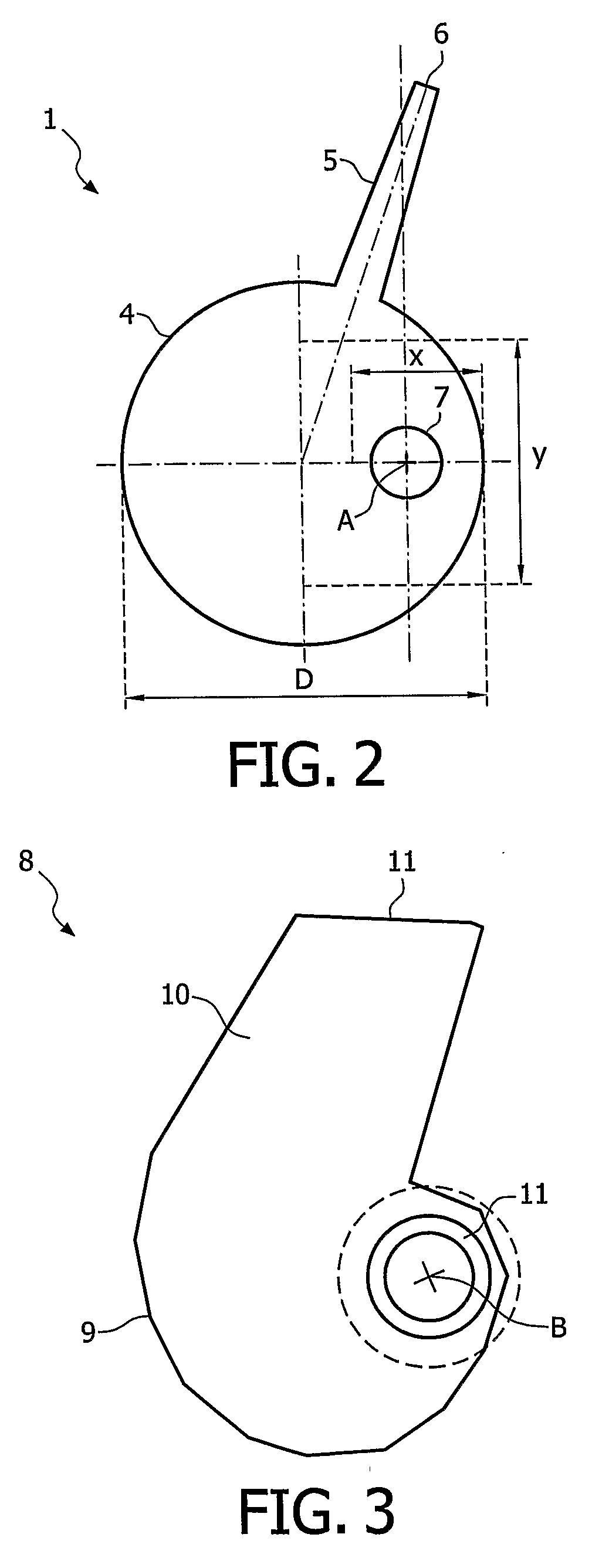
[0015] The container may have an arbitrary shape and geometry, provided that the container will have a permanent self-adjusting capacity. However, preferably, the container is substantially scroll-shaped (generally 6-shaped) or voluted, wherein the container can be formed by a scroll case. In this latter embodiment the discharge means is preferably coupled to an eccentric position of a lower part of the apparatus in order to optimize to an advantageous self-adjusting property on one side, and to maximize the possible
vertical displacement of the skimming mouth on the other side.
[0018] In a preferred embodiment, the discharge means comprises at least one
pipe, about which the container is mounted tiltably, said pipe aligning with and coinciding with an axis of rotation of the container. In operation, the container will swivel back and forth about the axis through its asymmetrical tilting self-adjustment evolutions. The direction, and the angle of the swiveling movement result from the difference between the incoming flow into the container and the flow out through the
effluent pipe. The construction provides a permanent self-adjusting, reliable and
stable system, independent on the orientation of the container, which is sensitive to considerable flow and liquid level variations. Conventional prior art devices use discharge means which are not connected to the container such as a hose inserted into the container or the discharge means is connected to the container in such a way that it restricts movement of the container, that is, the discharge means, which can be a pipe or hose, is not in operational engagement with the container such that they act independently. Therefore these dated prior art devices incorporating known discharge means are inefficient. The axial alignment of the discharge pipe, which is independently operationally engaged with the container of the present invention eliminates this restriction of movement.
[0019] In another preferred embodiment, the apparatus comprises bearing means at the
point of entry of the discharge pipe into the sidewall of the container that allows a circumferential tolerance gap or clearance between the bearing means, which can be a suitable
friction reducing bearing, made from suitable polymeric material, such as a TEFLON® material,
nylon material, etc., and the discharge pipe. The bearing may be in the form of an annular
coupling attached to the sidewall of the container such that the aperture in the sidewall of the container is larger than the inside
diameter of the bearing. In turn, it is preferred that the outside
diameter of the discharge pipe entering the sidewall also be slightly less than the inside
diameter of the bearing to provide for a circumferential gap that allows the liquid media to penetrate the gap into the container, thereby promoting the relative frictionless movement or uninhibited rotation of the container about the discharge pipe acting as the axis of rotation. In order to maintain its generally longitudinal orientation within the container and at the same time preventing the discharge pipe from axially displacing itself by
coming out of the sidewall of the container, the opposite end of the discharge pipe is loosely and axially connected to the opposite sidewall of the container in a manner that also allows for
free rotation of the opposite sidewall about the discharge pipe and further allows for a circumferential tolerance gap or predetermined clearance to allow liquid media to enter the container. This gap is preferably sufficiently large to allow contaminants suspended in the fluid media to enter the container through the gap spacing between the bearing and the discharge pipe. This feature prevents contaminants from
settling around the joint area and inhibiting the
free movement of the container about the discharge pipe.
[0022] In a preferable embodiment, which guarantees the automatic
adaptation of the device, a discharge pipe is supported in the side walls of the recessed part of the container for skimming off and the aperture, which is provided in the discharge pipe extends longitudinally between these side walls. For achieving optimal tilting movements of the container, in a favorable embodiment according to the invention, the container for skimming off is on one side wall provided with a bearing and sealing ring to which also the discharge pipe is made attachable. This makes it now possible that, in relation to the container, a protruding portion of the discharge pipe serves as a connecting sleeve e.g. to be coupled to a flexible discharge pipe of which the end portion may be mounted in a button end against the sliding ring without any friction, so as not to hinder the tilting movement of the skimming off container thereby. Another favorable embodiment of the device according to the invention is characterized in that one or more additional weight masses may be mounted to the skimming off container by which the extent of tilting movements may be altered.

