WDM hybrid splitter module

a splitter module and hybrid technology, applied in the field of wdm hybrid splitter modules, can solve the problems of halving communication distance, large investment, and inability to construct inexpensive systems, and achieve the effect of low equipment costs

Inactive Publication Date: 2008-02-07
SANTEC
View PDF2 Cites 43 Cited by
  • Summary
  • Abstract
  • Description
  • Claims
  • Application Information

AI Technical Summary

Benefits of technology

[0006] An object of the present invention is to realize a hybrid splitter module which is capable of improving a communication speed at low costs and low loss by upgrading a downlink signal to a WDM-PON and combining with a conventional device without adding any changes to a device on a subscriber side in a PON system.
[0016] According to the present invention with these features, a shift from a PON optical access transmission system to a WDM-PON system is allowed by changing a splitter without changing devices of an ONU in order to upgrade a transmission capacity. Therefore, an equipment investment to an ONU is not required, and an effect that allows upgrading to a next-generation optical network or a combination use therewith can be easily achieved. Since the number of ONUs is extremely large, it has considerable merits to require no changes in the ONU, so that a communication system of a PON system and a communication system of a WDM-PON system can be switched or used in combination at low equipment costs.

Problems solved by technology

However, in a case of simply replacing an existing PON communication system with the WDM, a huge investment is required because not only a splitter for link-up portion but also a terminal system of each ONU have to be changed.
There is a problem that an inexpensive system cannot be constructed because it is impossible to use a DFB (Distribution Feedback type) laser which does not require temperature adjustments in a WDM signal transmitter on an OLT side if a 1 ch bandwidth (1 dB width) of a WDM signal is 2.8 nm.
For this reason, there has been a problem that a communication distance is halved and replacement of a current system is difficult.

Method used


Image

  • WDM hybrid splitter module
  • WDM hybrid splitter module
  • WDM hybrid splitter module

Examples


embodiment 1

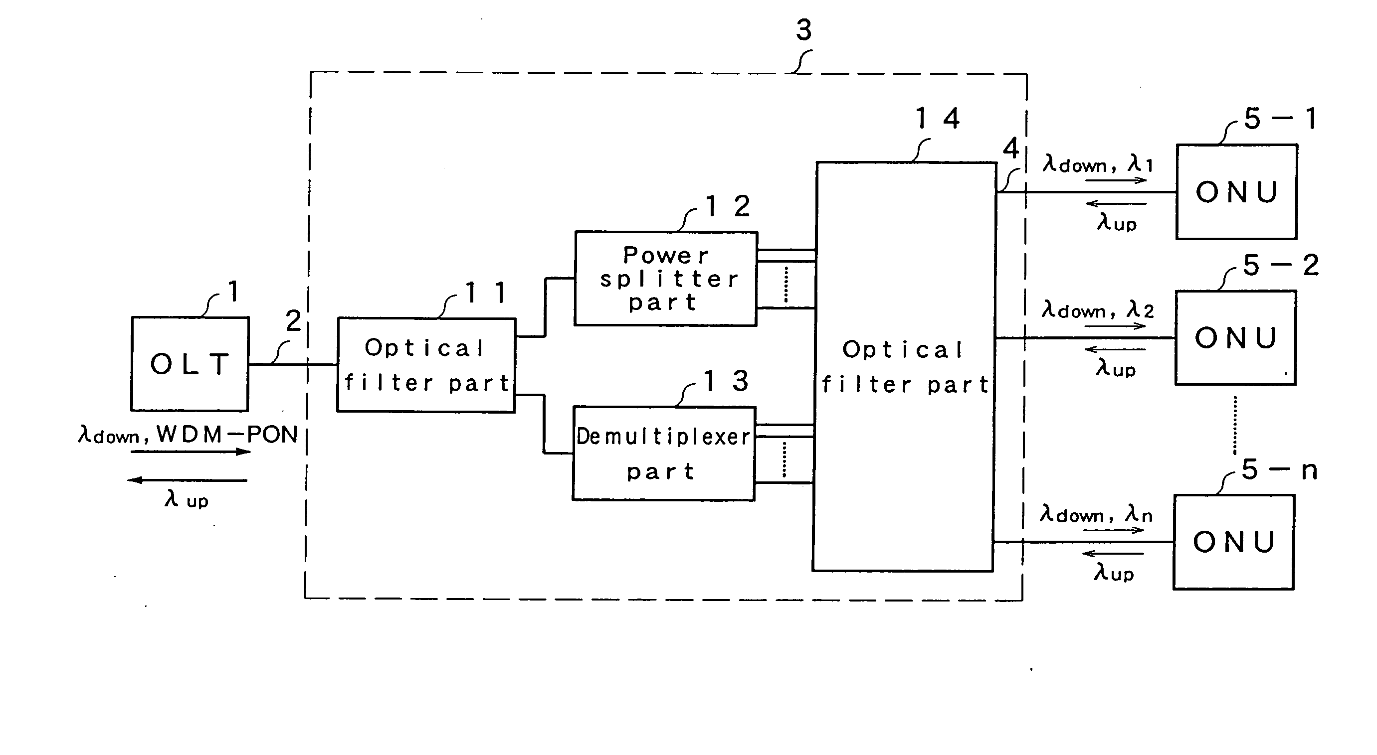
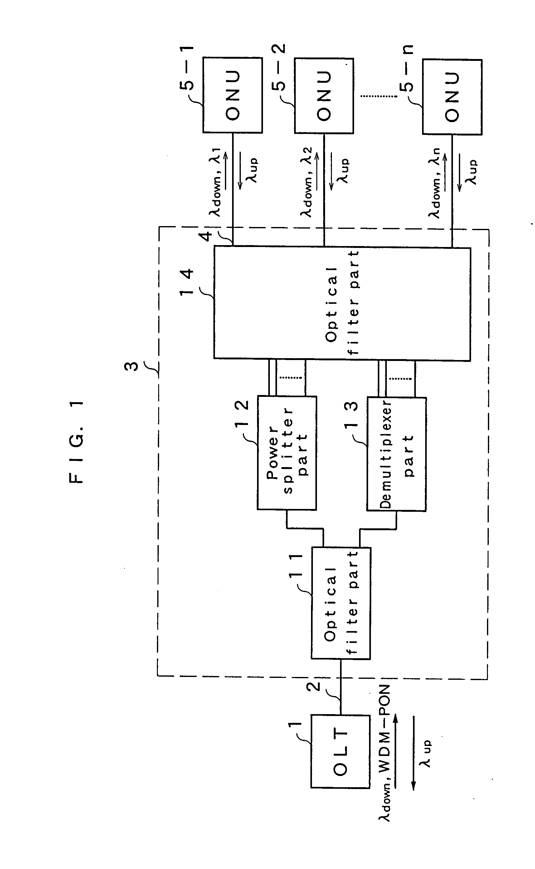
[0036]FIG. 1 is a configuration diagram showing a WDM hybrid splitter module according to embodiment 1 of the present invention. In FIG. 1, an OLT 1 is a transceiver of a station in an optical communication system, and connected to a WDM hybrid splitter module 3 via a single-mode optical fiber 2. The splitter module 3 is connected to a large number of ONUs 5-1 to 5-n of subscriber's devices via single-mode optical fibers 4. The OLT 1 transmits a downlink signal of a PON while receiving an uplink optical signal, and sends wavelength-multiplexed WDM-PON signals of λ1 to λn as a downlink signal. The ONUs 5-1 to 5-n receive a downlink signal in a PON wavelength bandwidth or a downlink signal in either one of the wavelengths of the WDM-PON signal to be obtained from the splitter module 3, and output a signal of an uplink wavelength bandwidth to a side of the splitter module 3.

[0037] Explained next will be the WDM hybrid splitter module 3. The WDM hybrid splitter module 3 is configured b...

embodiment 2

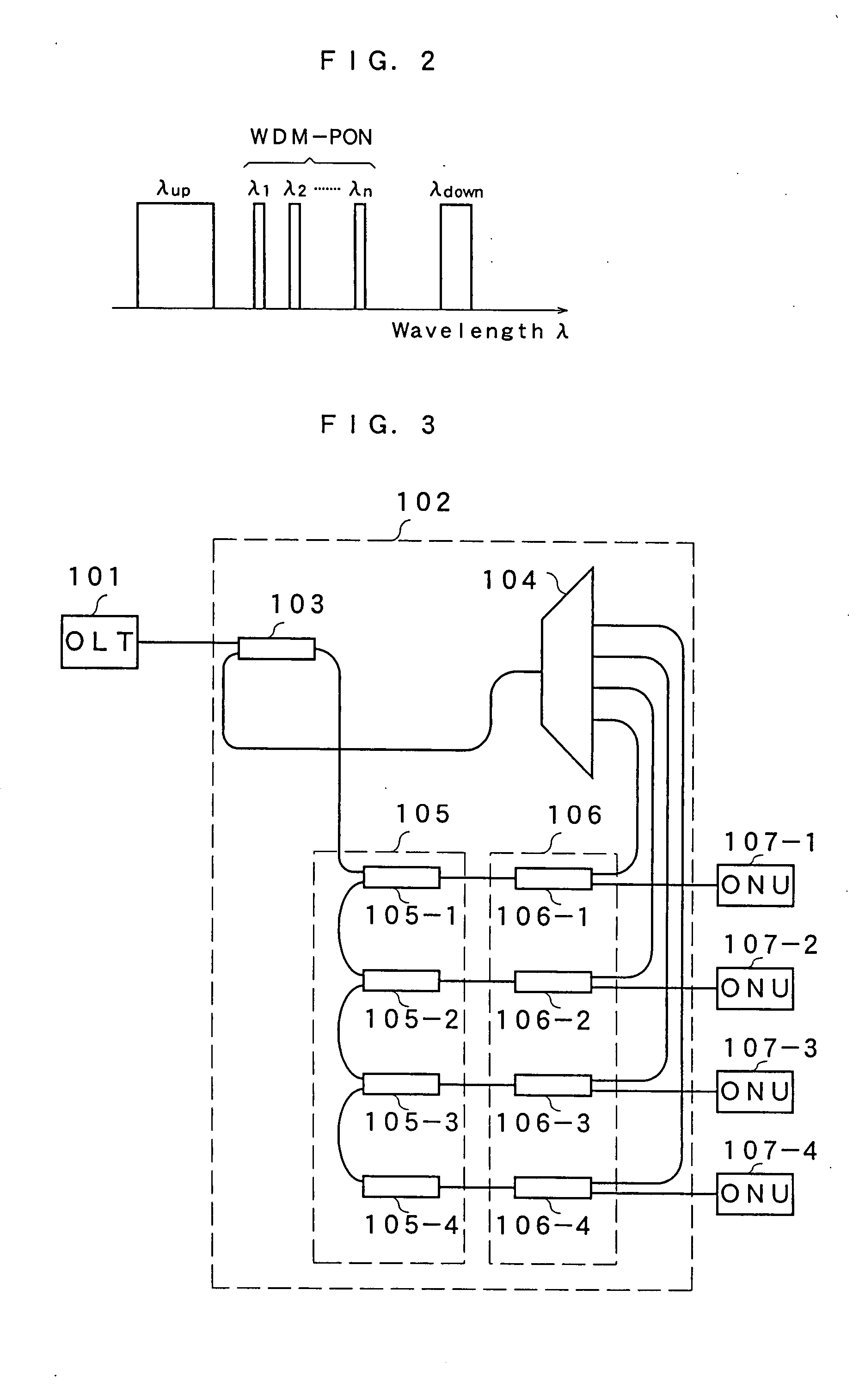
[0039] Next, explained below will be a more detailed embodiment according to the present invention. Embodiment 2 exhibits a WDM hybrid splitter module using a WDM-PON signal of four channels in a band of 1370 to 1480 nm with an interval of 20 nm. In the present embodiment, the module is used by being replaced with a G-PON splitter module, in which a WDM-PON bandwidth having a broad downlink transmission bandwidth can be used on a user's demand.

[0040]FIG. 3 is a configuration diagram of the WDM hybrid splitter module according to embodiment 2. In FIG. 3, an OLT 101 is connected to an input port of a WDM hybrid splitter module 102 by a single-mode optical fiber. A first optical filter part 103 is configured by a dielectric multilayered film filter with a total film thickness of 39.6 μm in which Ta2O5 having a refractive index of 2.09 and SiO2 having a refractive index of 1.48 are alternately laminated for a total of 127 layers, for example, on a glass substrate transparent in an infr...

embodiment 3

[0045] Embodiment 3 exhibits a WDM hybrid splitter module using a downlink signal of 8 ch in a band of 1370 to 1480 nm with an interval of 10 nm as the WDM signal 202. FIG. 5 shows a configuration diagram of the WDM hybrid splitter module according to embodiment 3. In embodiment 3, a WDM-PON signal having eight channels of λ1 to λ8 with an interval of 10 nm in a band of 1370 to 1480 nm is used. In embodiment 3, a signal from an OLT 121 is added to a first optical filter 103 of a WDM hybrid splitter module 122, and a signal in a PON bandwidth is separated and added to a power splitter part 123. The power splitter part 123 is a splitter which divides a downlink signal of an inputted signal bandwidth equally into eight, and each output thereof is inputted to each filter of a WDM module group 124. The WDM module group 124 is realized by integrating the above-described demultiplexer part and the second optical filter part, and composed of eight WDM modules 124-1 to 124-8 having one input...


PUM


Abstract

A downlink signal and WDM-PON signal from an OLT 1 are separated by an optical filter part 11, and a downlink signal is split by a power splitter part 12. A WDM-PON signal is also split in each wavelength by a demultiplexer part 13, and a downlink signal and a WDM-PON signal of either one of the wavelengths are outputted to each ONU, in an optical filter part 14. Moreover, an uplink signal from the ONU is introduced to the power splitter part 12 via the optical filter part 14, and outputted to the OLT 1 via the optical filter part 11. Therefore, it is possible to realize a hybrid splitter module which allows upgrading a downlink signal to a WDM-PON without adding changes to a device on a subscriber side.

Description

CROSS REFERENCE TO RELATED APPLICATION [0001] This application is a nonprovisional application of U.S. Provisional Patent Application No. 60 / 833,782 filed on Jul. 28, 2006, currently pending. The disclosure of U.S. Provisional Patent Application No. 60 / 833,782 is hereby incorporated by reference.1. FIELD OF THE INVENTION [0002] The present invention relates to a WDM hybrid splitter module used in a communication system. 2. DISCUSSION OF THE RELATED ART [0003] A PON (Passive Optical Network) is one of optical subscriber network construction systems, being a system for distributing light so that an OLT (Optical Line Terminal) which is a transceiver on a station side can connect to a plurality of ONUs (Optical Network Units) on a user side. Since a signal transmitted from a base station by an optical fiber is divided by a splitter module in a PON system as described above, cable costs can be reduced in comparison with a system for providing an optical fiber from an OLT to each ONU one ...

Claims


Application Information

Patent Timeline
Patent Type & Authority Applications(United States)
IPC IPC(8): H04J14/00
CPCG02B6/12007G02B6/29361G02B6/29362G02B6/29365H04J14/02G02B6/2937G02B6/2938G02B2006/12109G02B6/29367
Inventor OKUDA, RYOUSUKEUEHARA, NOBORUMEKADA, NAOYUKIMIYAKOSHI, TAIHEI
Owner SANTEC
Why Eureka
Try Eureka