
Cooling Device and Cooling Method for Fuel Cell

a fuel cell and cooling device technology, applied in the direction of fuel cells, electrical appliances, electrochemical generators, etc., can solve the problem that the electric conductivity can eventually exceed the allowed limit, and achieve the effect of decreasing the electric conductivity of the coolant, reducing the quantity of electric conductivity, and reducing the electric conductivity

Active Publication Date: 2008-02-07
TOYOTA JIDOSHA KK
View PDF2 Cites 28 Cited by
  • Summary
  • Abstract
  • Description
  • Claims
  • Application Information

AI Technical Summary

Benefits of technology

[0006]Accordingly, it is an object of the present invention to provide a device for cooling a fuel cell that can maintain the electric conductivity of a liquid coolant within the predetermined range even if the temperature of the liquid coolant changes following the change in the operation state of the fuel cell.
[0015]For example, it is preferred that the cooling device further comprise electric conductivity decreasing means for decreasing the electric conductivity of the coolant, wherein the parameter related to the coolant temperature is controlled based on the decrease quantity of the electric conductivity with the electric conductivity decreasing means. Generally the decrease in electric conductivity with the electric conductivity decreasing means depends on the amount of coolant that came into contact and passed through the electric conductivity decreasing unit, and if the treatment capacity of the electric conductivity decreasing means is increased, then the change in the electric conductivity caused by the electric conductivity decreasing unit will be large. Therefore, in this case, the electric conductivity at the target set temperature can be estimated by considering the amount of decrease in the electric conductivity caused by the electric conductivity decreasing means and more accurate control electric conductivity is possible.
[0016]Here, the “electric conductivity reducing means” is a unit that can decrease electric conductivity by ion exchange between the ionized impurities and hydrogen ions or hydroxide ions; units of various types can be employed, but means having a filter structure using, for example, an ion-exchange resin, is especially easy to use.

Problems solved by technology

Therefore, if the ratio of a liquid coolant passing through the electric conductivity decreasing device at a high temperature is small, the electric conductivity eventually can exceed the allowed limit.

Method used


Image

  • Cooling Device and Cooling Method for Fuel Cell
  • Cooling Device and Cooling Method for Fuel Cell
  • Cooling Device and Cooling Method for Fuel Cell

Examples


embodiment 1

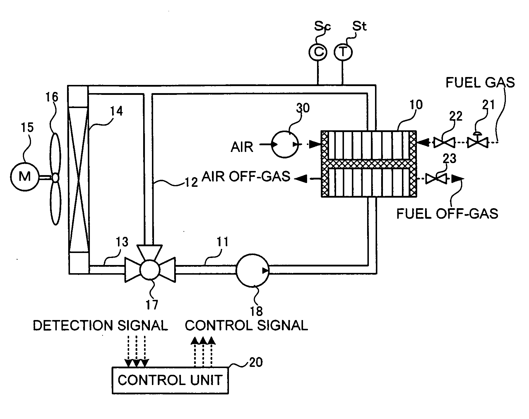
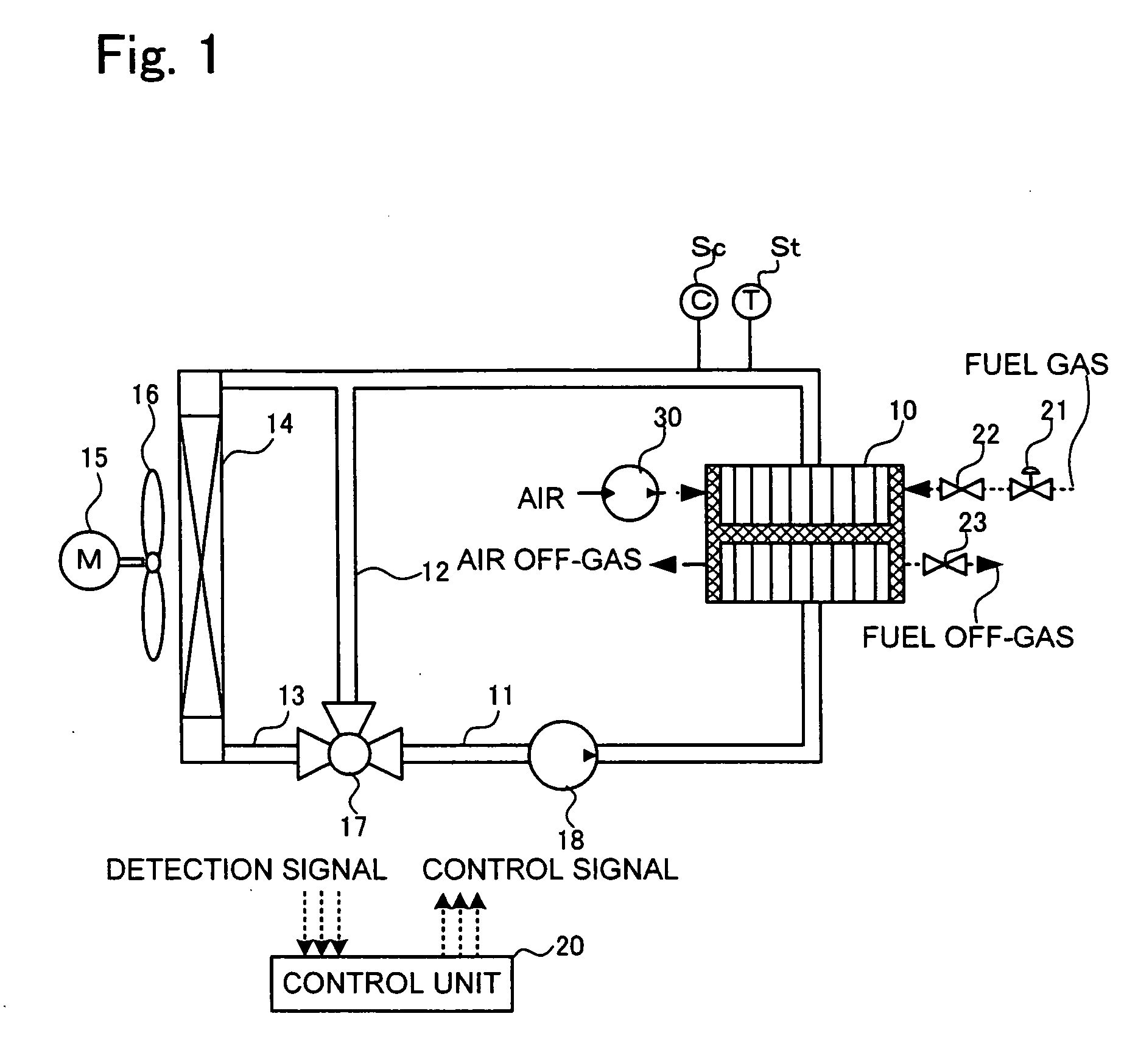
[0030]Embodiment 1 of the present invention relates to cooling control in the case where direct decrease in the electric conductivity by electric conductivity decreasing device is not taken into account. FIG. 1 shows the entire configuration of the present fuel cell system. As shown in FIG. 1, in the fuel cell system, a circulation channel 11 of a liquid coolant is provided so that the liquid coolant can be circulated inside a fuel cell stack 10. The circulation channel 11 is divided into a bypass channel 12 and a cooling channel 13 where a radiator 14 is provided. The circulation channel is configured so that the bypass channel 12 and cooling channel 13 can be selected by a three-way valve 17. A liquid coolant pump 13 that is driven at a revolution speed based on a control signal from a control unit 20 is provided in the circulation channel 11, thereby enabling forced circulation of the liquid coolant. A thermometer St for detecting the temperature of the liquid coolant and an elec...

embodiment 2

[0058]Embodiment 2 of the present invention, by contrast with Embodiment 1, relates to a cooling control which employs an electric conductivity decreasing device and takes the direct decrease in electric conductivity into account. FIG. 5 illustrates the entire configuration of the present fuel cell system. As shown in FIG. 5, in this fuel cell system, an ion exchanger 19, which is equivalent to the electric conductivity decreasing device in accordance with the present invention, is provided in the circulation channel 11 of a liquid coolant in Embodiment 1. Furthermore, a heat exchanger 30 is provided in the circulation channel 11, and a secondary cooling device serving to conduct heat exchange via this heat exchanger with the liquid coolant flowing through the circulation channel 11, which is a primary channel, is provided. The secondary cooling device comprises a pressure adjusting valve 31, a condenser 32, and a circulation pump 33 and is so configured that heat can be taken by th...


PUM


Abstract

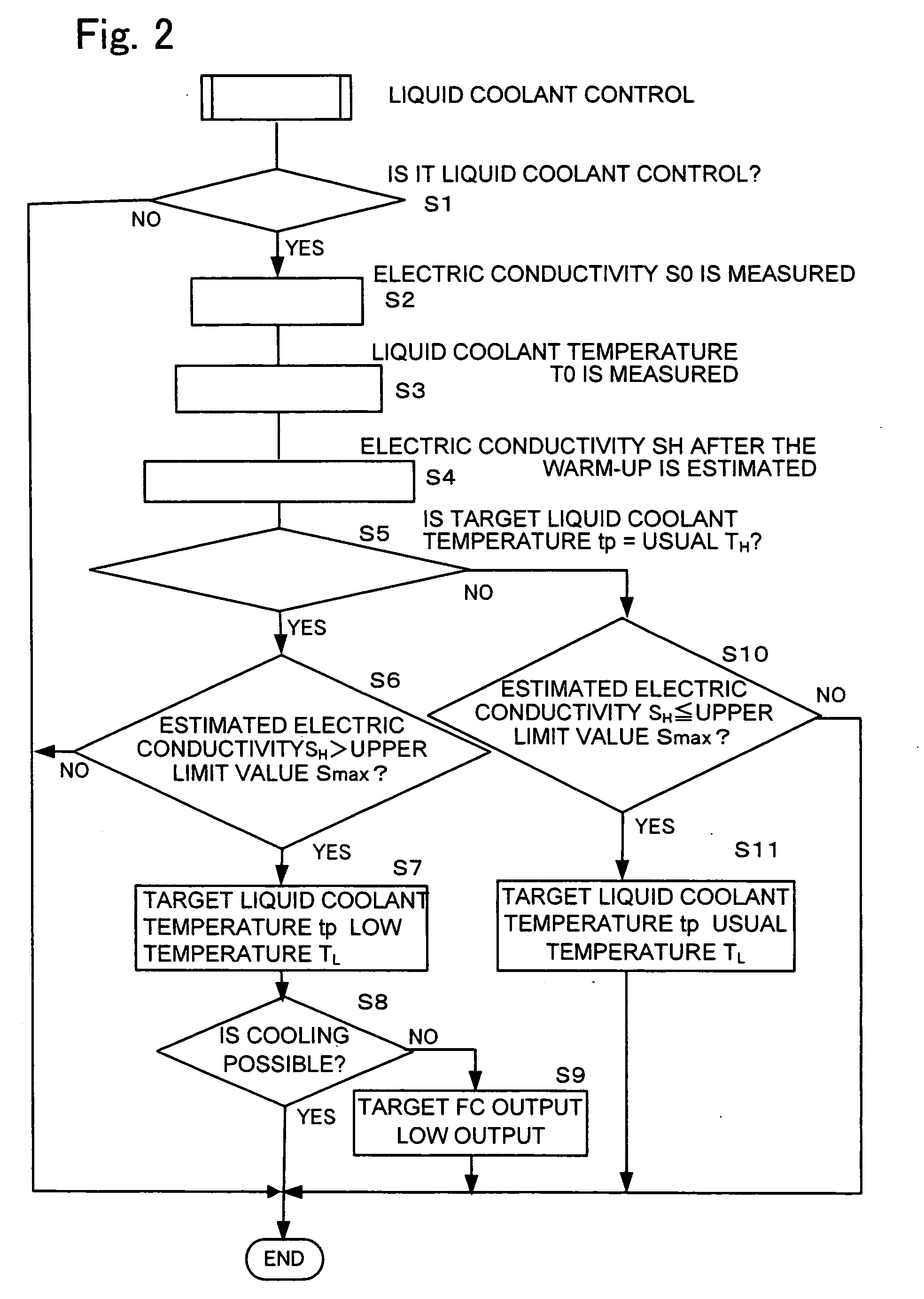
A cooling device for a fuel cell is provided which can maintain the electric conductivity of a liquid coolant within the predetermined range even if a load suddenly changes. In the cooling device for a fuel cell (10), the parameters (TH, TL) relating to the coolant temperature can be controlled so that the electric conductivity (S) at a target set temperature is maintained within a target electric conductivity range (Smax-Smin) based on the correlation between the parameters relating to the coolant temperature and the electric conductivity of the coolant. Because the electric conductivity is feed-forward controlled based on the correlation between the parameters relating to the coolant temperature and the electric conductivity of the coolant, the electric conductivity of the coolant can be reliably maintained within the target range even when electric conductivity with a comparatively poor responsiveness is controlled.

Description

TECHNICAL FIELD[0001]The present invention relates to a device for cooling a fuel cell system, and more particularly to a cooling device for estimating electric conductivity and controlling the temperature of liquid coolant.BACKGROUND ART[0002]Cooling devices with a circulating liquid coolant have been used to remove the heat generated in fuel cells in the fuel cell systems installed on movable objects such as electric automobiles.[0003]For example, Japanese Paten Application Laid-open No. 2002-216817 disclosed such cooling device which decreases the liquid coolant bypass ratio to an electric conductivity reduction device (ion-exchange resin) when the temperature of the liquid coolant is high and electric conductivity is low, and increases the bypass ratio to the electric conductivity reduction device when the temperature of the liquid coolant is low and electric conductivity is high. With such technology, at a high temperature when high cooling performance is required, the bypass f...

Claims


Application Information

Patent Timeline
IPC IPC(8): H01M8/04
CPCY02E60/50H01M8/04029
Inventor FUJITA, NOBUO
Owner TOYOTA JIDOSHA KK
Learn More