
Compact fuel cell

a fuel cell and compact technology, applied in the field of compact fuel cells, can solve the problems of damage to the materials making up the fuel cell, and achieve the effects of decreasing the electrical conductivity of the coolant, and decreasing the electrical conductivity

Inactive Publication Date: 2014-01-16
COMMISSARIAT A LENERGIE ATOMIQUE ET AUX ENERGIES ALTERNATIVES
View PDF5 Cites 16 Cited by
  • Summary
  • Abstract
  • Description
  • Claims
  • Application Information

AI Technical Summary

Benefits of technology

The present invention aims to provide a fuel cell with a fluid management system that has less space requirement than existing assemblies.

Problems solved by technology

Indeed, if the operating temperature is too low, the best operating efficiency of the fuel cell could not be achieved, and if the fuel cell undergoes a too high temperature rise, the materials making up the fuel cell can be damaged.

Method used


Image

  • Compact fuel cell
  • Compact fuel cell
  • Compact fuel cell

Examples


Embodiment Construction

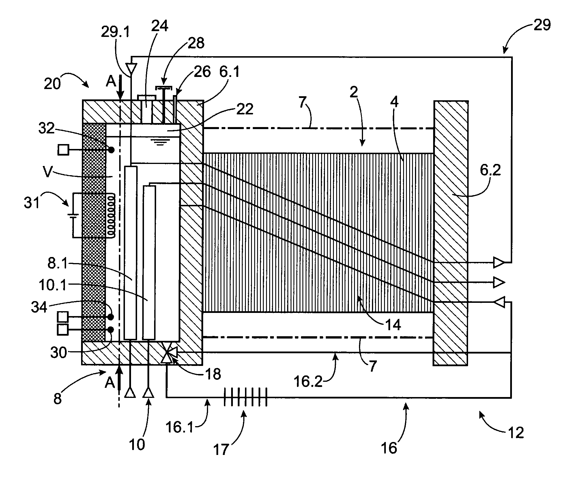
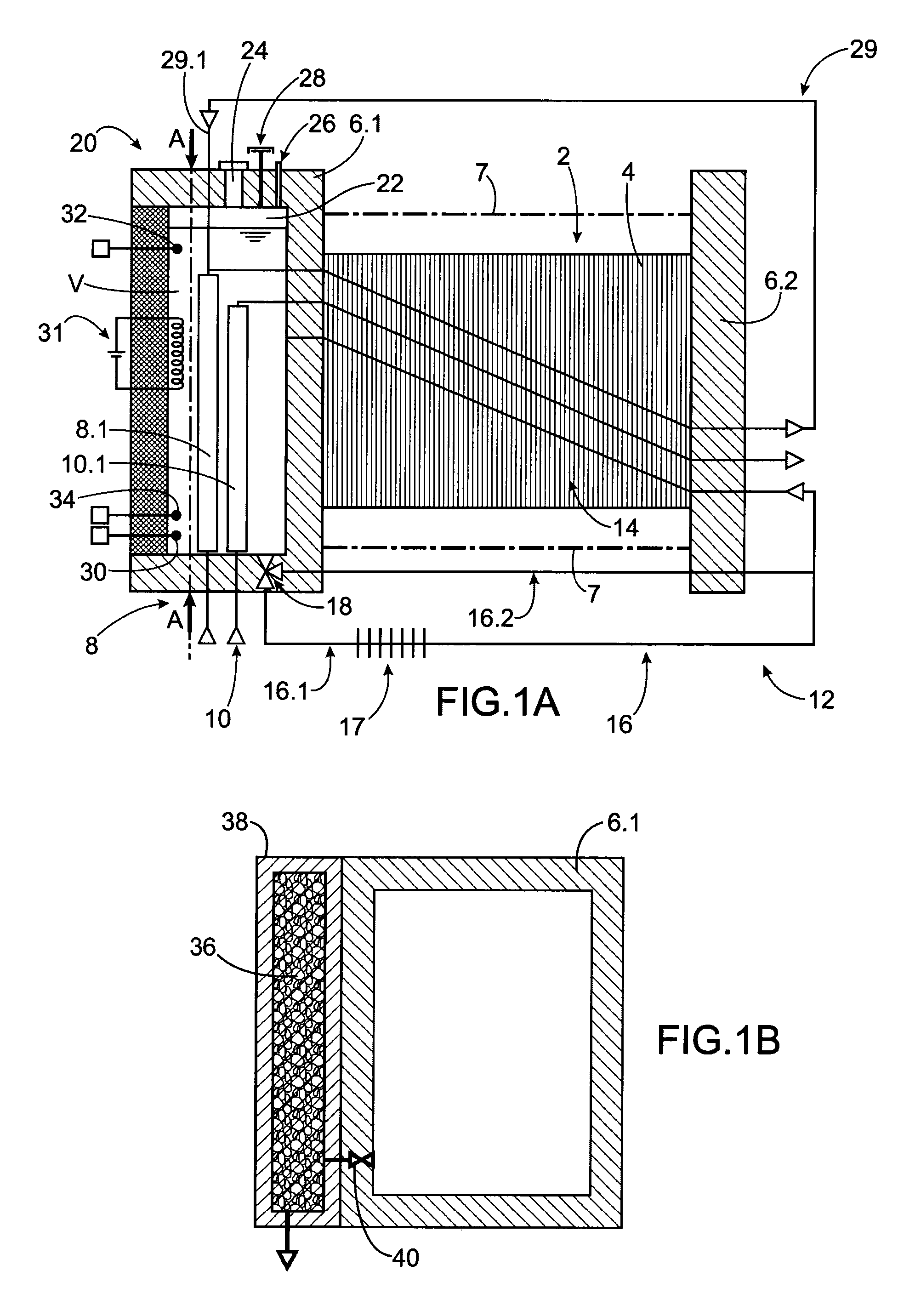
[0041]In FIG. 1A, a schematic representation of an exemplary embodiment of a fuel cell according to the present invention can be seen.

[0042]In the description that follows, a proton exchange membrane fuel cell or Polymer Exchange Membrane Fuel Cell (PEMFC) will be described in particular. The fuel gas is then hydrogen and the oxidizing gas is air or oxygen. However, this description is in no way limiting and the invention is applicable to any type of fuel cell.

[0043]The fuel cell comprises a stack 2 of electrochemical cells 4 consisting of bipolar plates and ion exchange membranes alternately provided, and two end plates 6.1, 6.2 on either side of the stack. The end plates 6.1, 6.2 are connected by tie rods 7 and exert a compressive strain to the stack 2 to ensure an evenly distributed electrical conduction throughout the surface of the elements making up the cells.

[0044]The fuel cell comprises a circuit 8 for supplying hydrogen to the cells and a circuit 10 for supplying air or oxy...


PUM

PropertyMeasurementUnit
temperatureaaaaaaaaaa
operating temperatureaaaaaaaaaa

Abstract

A fuel cell including a stack of electrochemical cells and first and second end plates, an inside circuit for flowing deionized water inside the stack connected to an outside circuit for flowing deionized water outside the stack, the deionized water forming a coolant, a circuit for supplying hydrogen to the cells and a circuit for supplying air to the cells, and a casing mounted to the first end plate and forming a tight volume at least partially filled with water where the inside circuit emerges for flowing the coolant. The circuits for supplying air and hydrogen pass through the tight volume and are dipped into the deionized water to exchange heat with the deionized water. A portion of the supply circuit enables air to be humidified with water contained in the tight volume.

Description

TECHNICAL FIELD AND PRIOR ART[0001]The present invention relates to a compact fuel cell.[0002]A fuel cell, to deliver electricity, is supplied with fuel gas, for example hydrogen in the case of a proton exchange membrane fuel cell (PEMFC), and with oxidizing gas, for example air or oxygen. The operation of the fuel cell also results in generating heat energy.[0003]A fuel cell comprises a stack of electrochemical cells, each cell comprising an anode and a cathode. The cells are kept compressed against each other by end plates connected by the tie rods[0004]A circuit is provided to supply reactive gases to the cells. Those reactive gases should be brought to the fuel cell under preset temperature, pressure and moisture conditions. The fuel cell therefore comprises devices for controlling pressure, temperature and moisture of the oxidizing gas and devices for controlling pressure, temperature of the fuel gas. Generally, the moisture content of the oxidizing gas is controlled by an air-...

Claims


Application Information

Patent Timeline
Patent Type & Authority Applications(United States)
IPC IPC(8): H01M8/04
CPCH01M8/04134H01M8/1007D01D5/40D01F2/00D01F2/24D01F2/28H01M8/04029H01M8/04037H01M8/04044H01M8/04074H01M8/04149H01M8/04201H01M8/04373H01M8/04656H01M2008/1095B60L2200/26Y02E60/50H01M8/02H01M8/04H01M8/10
Inventor DROUHAULT, DELPHINENIVELON, PIERRE
Owner COMMISSARIAT A LENERGIE ATOMIQUE ET AUX ENERGIES ALTERNATIVES
Learn More