Amphibious robotic device

a robotic device and amphibious technology, applied in the field of amphibious robotic devices, can solve the problems of affecting the maintenance and affecting the operation of the pose on land, and achieving the computationally straightforward task of posing maintenance a lot more difficul

Active Publication Date: 2008-02-07
MCGILL UNIV
View PDF13 Cites 34 Cited by
  • Summary
  • Abstract
  • Description
  • Claims
  • Application Information

AI Technical Summary

Benefits of technology

[0010]Also in accordance with the present invention, there is provided a robotic device for navigating in at least a liquid medium, the robotic device comprising a body, a legged propulsion system having a series of legs external of the body, each of said legs being driven by an actuator and mounted to the body for pivotal movement about a respective transverse axis, each of the legs being operable to at least oscillate relative to the body about the respective transverse axis such that interaction between the legs and the liquid medium produces propulsive forces that displace the robotic device within the liquid medium, and a control system allowing the robo

Problems solved by technology

In general, underwater robotics poses certain unique challenges that render many of the principles of terrestrial robotics problematic.
A robot underwater is able to move along six degrees of freedom, and maneuvering with six degrees of freedom creates serious complications.
A computationally straightforward task of pose maintenance on land becomes far more challenging under water, because of environmental factors such as strong currents in marine environments.
Infra-red sensors lose some of their effectiveness in water as well.
Wireless radio communications are also impossible over a large distance in water compared to ground based control.
All these issues make underwater robotics problems more difficult than terrestrial robotics.
Although simple by design, these vehicles lack the maneuverability and

Method used


Image

  • Amphibious robotic device
  • Amphibious robotic device
  • Amphibious robotic device

Examples


Embodiment Construction

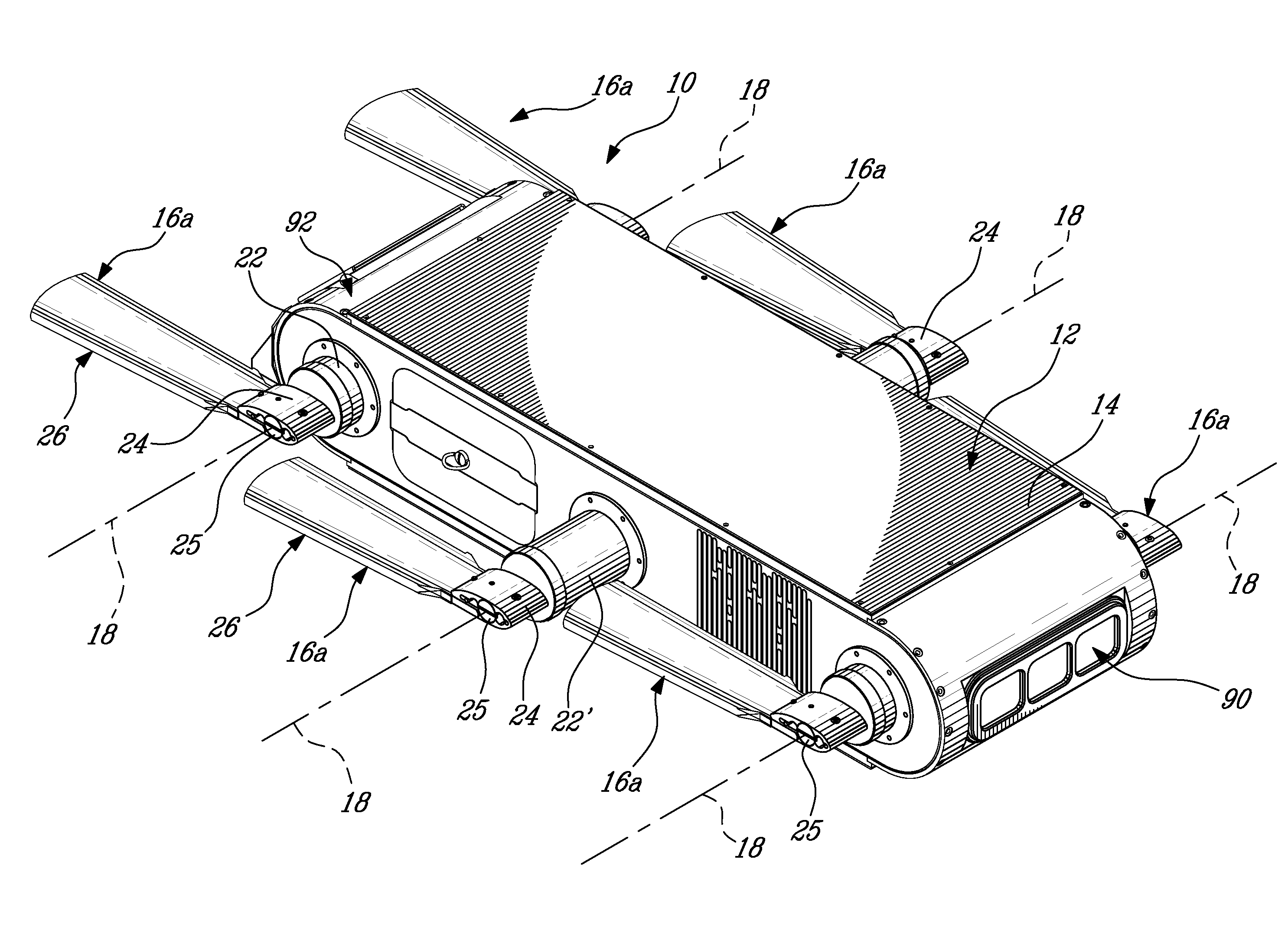
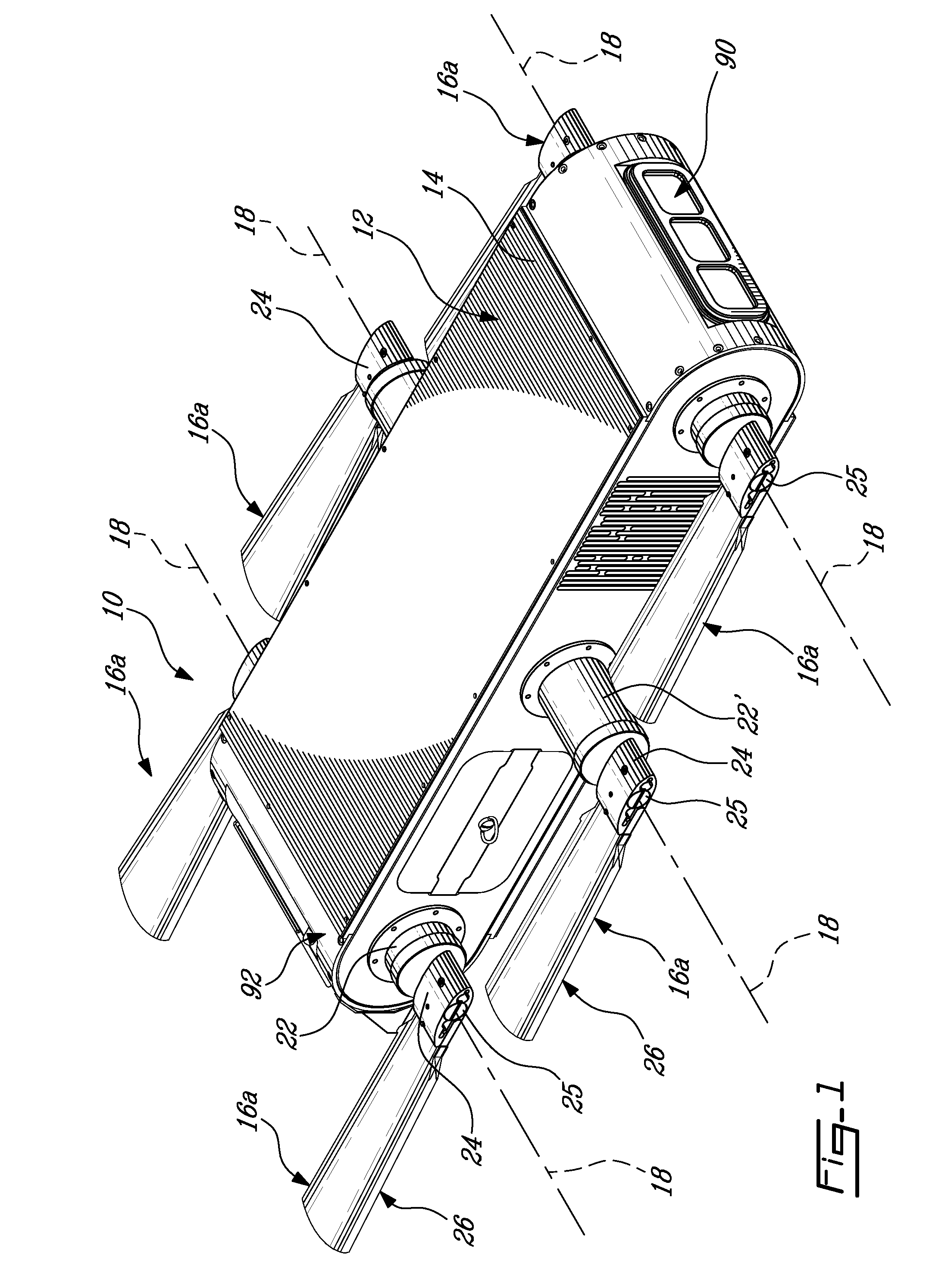
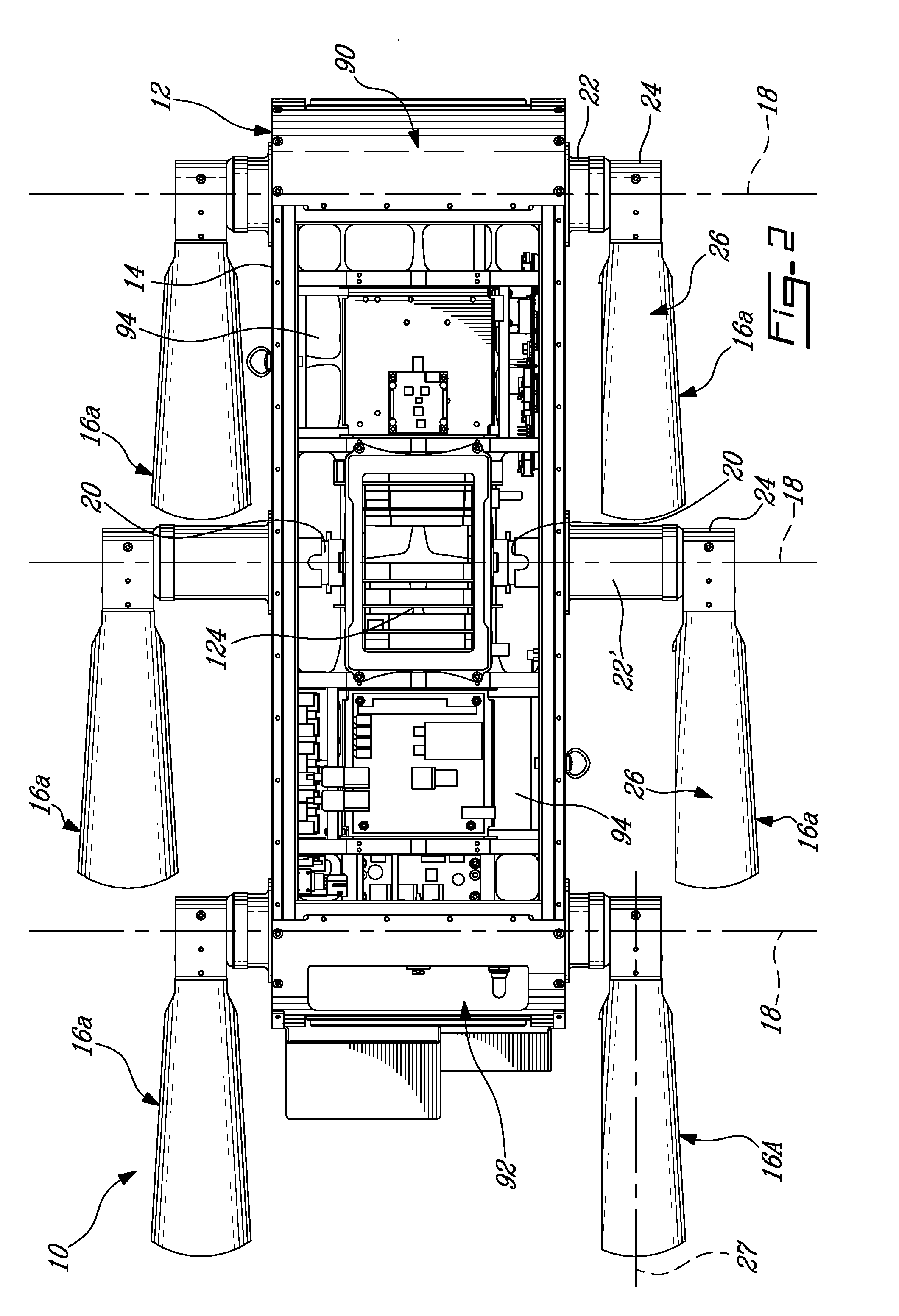
[0029]Referring to FIGS. 1-2, a robotic device in accordance with a particular embodiment of the present invention is generally shown at 10. The device 10 is designed as an aquatic swimming robot that is also capable of operating on a solid medium, including compact ground surfaces and sand. As such, the device 10 is said to be amphibious in that it can walk on a solid surface and penetrate a neighboring liquid medium, swim in that liquid medium and exit the liquid medium on an appropriate interface between the solid and liquid medium (e.g. a ramped up bottom surface of the liquid environment becoming the solid medium such as a beach).

[0030]The device 10 comprises a body 12 including a waterproof shell 14 which can be for example made of aluminum, inside which all electronics, sensors, power supplies, actuators, etc. are housed. The shell 14 includes buoyancy plates which allows for the buoyancy of the device 10 to be adjusted depending on the properties of the liquid medium the dev...


PUM


Abstract

A control system for a robotic device maneuverable in at least a liquid medium, the system having at least one visual sensor retrieving an image of the device's environment, an image analyzing module receiving the image, determining a presence of an object of a given type therein and analyzing at least one property of the object, a motion calculator determining a desired motion of the device based on the property, and a controller operating a propulsion system of the device to obtain the desired motion. Also, a legged robotic device having a control system including at least one sensor providing data about an environment of the device, the control system using sensor data to determine a desired motion of the device, determining a corresponding required leg motion of each of the legs to produce the desired motion and actuating the legs in accordance with the corresponding required leg motion.

Description

FIELD OF THE INVENTION[0001]The present invention relates to robotic devices, particularly to robotic devices designed to maneuver in a liquid medium as well as on a solid medium.BACKGROUND ART[0002]In general, underwater robotics poses certain unique challenges that render many of the principles of terrestrial robotics problematic. A robot underwater is able to move along six degrees of freedom, and maneuvering with six degrees of freedom creates serious complications. A computationally straightforward task of pose maintenance on land becomes far more challenging under water, because of environmental factors such as strong currents in marine environments. Infra-red sensors lose some of their effectiveness in water as well. Wireless radio communications are also impossible over a large distance in water compared to ground based control. All these issues make underwater robotics problems more difficult than terrestrial robotics.[0003]The traditional approach used to propel undersea v...

Claims


Application Information

Patent Timeline
IPC IPC(8): B60F3/00
CPCB63C11/42B60F3/0007
Inventor DUDEK, GREGORYPRAHACS, CHRISSAUNDERSON, SHANEGIGUERE, PHILIPPESATTAR, JUNAEDJENKIN, MICHAEL
Owner MCGILL UNIV
Why Eureka
Try Eureka