Method for operating an internal combustion engine, and associated internal combustion engine

Inactive Publication Date: 2008-02-14
DAIMLER AG
View PDF12 Cites 14 Cited by
  • Summary
  • Abstract
  • Description
  • Claims
  • Application Information

AI Technical Summary

Benefits of technology

[0006] In a method for operating an internal combustion engine including inlet valves with variably adjustable opening curves, during part-load operation, the closing time of the inlet valves and the fu

Problems solved by technology

With such an exhaust gas recirculation, however, there is the problem that, with an increasing recirculation rate, the risk of contamination or coking in particular of an exhaust gas cooler which is s

Method used


Image

  • Method for operating an internal combustion engine, and associated internal combustion engine
  • Method for operating an internal combustion engine, and associated internal combustion engine
  • Method for operating an internal combustion engine, and associated internal combustion engine

Examples


Embodiment Construction

[0025] In the figures, identical components are provided with the same reference symbols.

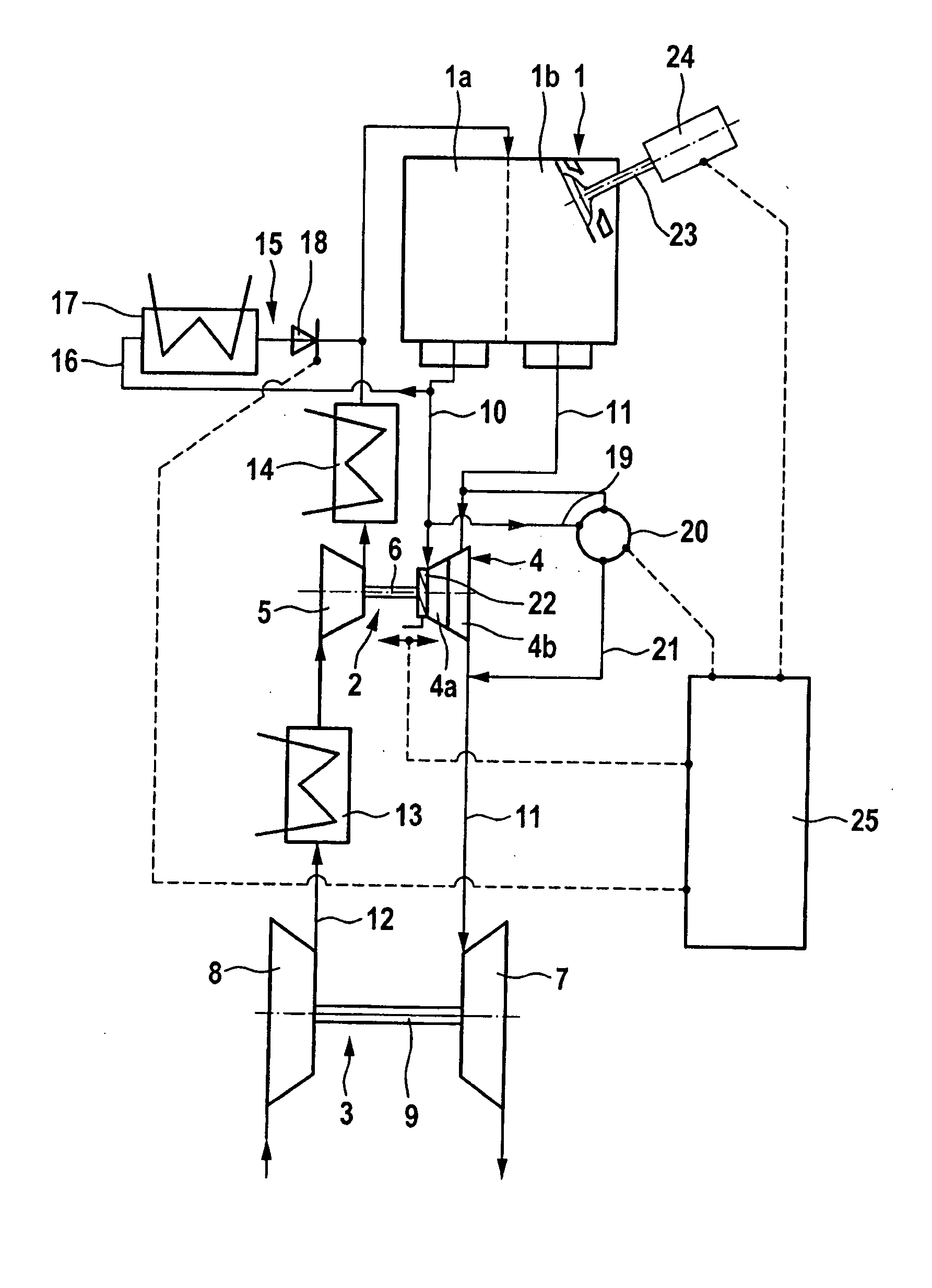
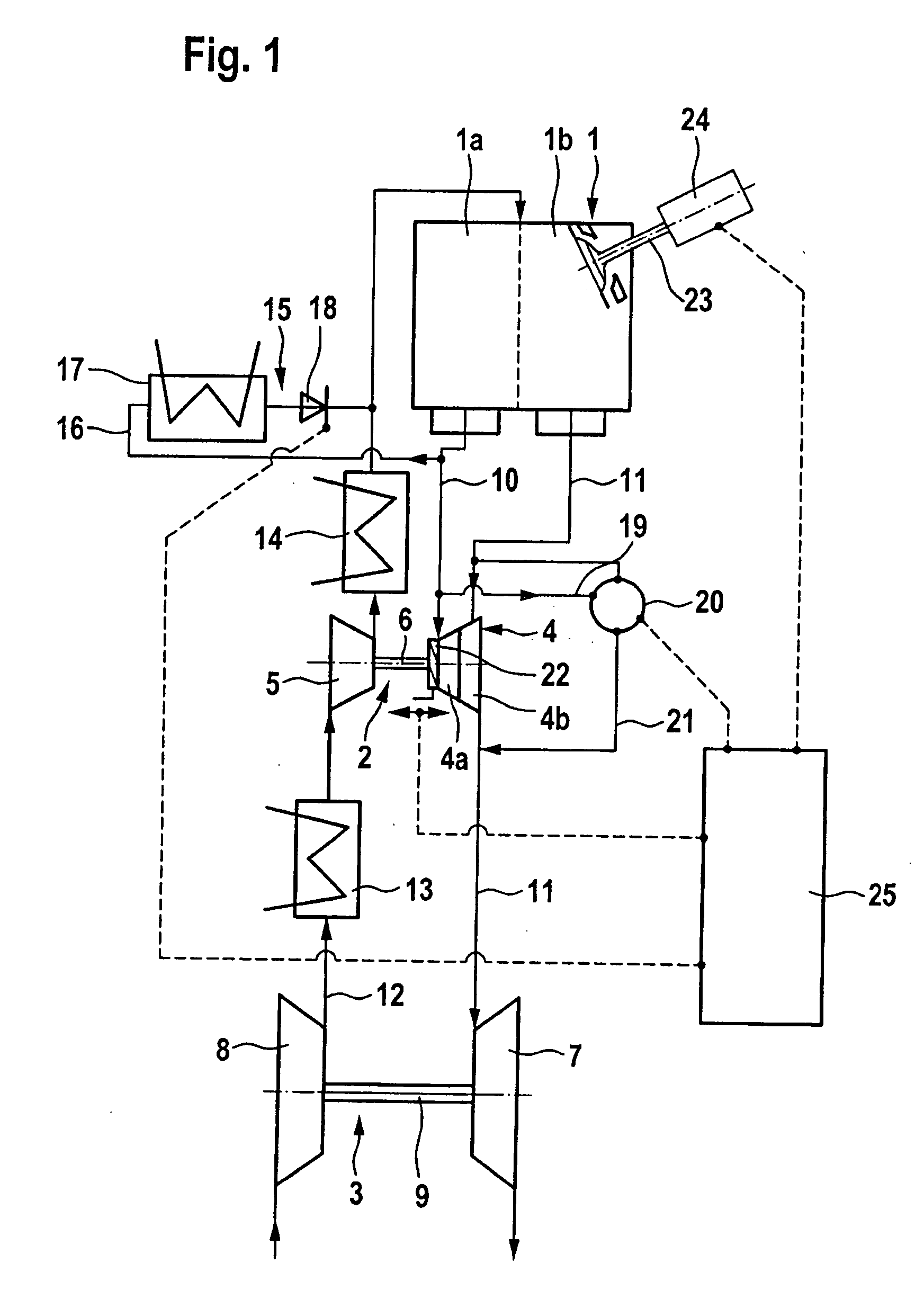
[0026] The internal combustion engine 1—a spark-ignition engine or a diesel engine—illustrated in FIG. 1 is equipped with two series connected exhaust gas turbochargers 2 and 3, of which the exhaust gas turbocharger 2 which is arranged close to the engine assumes the function of a high-pressure turbocharger and the exhaust gas turbocharger 3, which is arranged remote from the engine, assumes the function of a low-pressure turbocharger. The high-pressure turbocharger is of smaller size than the low-pressure turbo-charger and therefore has a lower mass moment of inertia.

[0027] The exhaust gas turbocharger 2 close to the engine comprises an exhaust gas turbine 4 in the exhaust system of the internal combustion engine, the turbine wheel of which exhaust gas turbine is connected by means of a shaft 6 to the compressor wheel in the compressor 5 in the intake tract 12. The exhaust gas turbine 4 is of...


PUM


Abstract

In a method for operating an internal combustion engine including inlet valves with variably adjustable opening curves, during part-load operation, the closing time of the inlet valves and the fuel injection time are controlled as a function of the cylinder internal temperature so as to maintain the cylinder internal temperature relatively low in a controllable manner for reducing NOx emissions.

Description

[0001] This is a Continuation-In-Part Application of pending International Patent Application PCT / EP2006 / 001820 filed Feb. 28, 2006 and claiming the priority of German Patent Application 10 2005 012 306.6 filed Mar. 17, 2005.BACKGROUND OF THE INVENTION [0002] The invention relates to a method for operating an internal combustion engine having intake and exhaust valves the opening of the intake valve being adjustable depending on the engine operating conditions. [0003] U.S. Pat. No. 6,688,280 B2 discloses a method for the reduction of nitrogen oxides which are generated during fired operation of an internal combustion engine. Here, full closing of the inlet valves of the cylinders is delayed such that, at the beginning of the compression stroke, the inlet valve remains in the open position and a part of the combustion air which has already been introduced into the combustion chamber can flow back again via the open inlet valve into the upstream air collector. In this way, both the co...

Claims


Application Information

Patent Timeline
IPC IPC(8): F01L31/00F01N13/10
CPCF02D13/0234F02D13/0261F02D13/0269Y02T10/47F02D41/006F02D41/0065Y02T10/142F02D15/04Y02T10/12Y02T10/40
Inventor SCHMID, WOLFRAMSUMSER, SIEGFRIED
Owner DAIMLER AG
Why Eureka
Try Eureka