Heat Dissipating LED Signal Lamp Source Structure

a technology of led signal lamps and source structures, which is applied in the field of led signal lamps, can solve the problems of affecting pedestrian judgment, increasing the chance of accidents, and accumulating a large amount of heat in the signal lamp structure, so as to enhance the light emitting efficiency and life expectancy, and dissipate heat.

Inactive Publication Date: 2008-02-14
PYROSWIFT HOLDING CO LIMITED
View PDF2 Cites 152 Cited by
  • Summary
  • Abstract
  • Description
  • Claims
  • Application Information

AI Technical Summary

Benefits of technology

[0009]Therefore, the present invention is to provide an LED signal lamp emitting source structure having a heat dissipating structure that uses a single light emitting unit as the signal lamp emitting source, and the light emitting unit has a heat dissipating structure disposed at the periphery of the light emitting unit to dissipate the heat produced by the light emitting unit to the outside, Besides substituting a plurality of traditional light emitting units by a single light emitting unit, the present invention also provides a design of a heat dissipating structure to enhance the light emitting efficiency and the life expectancy of the light emitting unit.
[0010]The present invention provides an LED signal lamp emitting source structure that comprises an isothermal board being a highly thermal conducting disc, a light emitting unit disposed on th

Problems solved by technology

However, the traditional signal lamp structure that emits light by bulbs may be sheltered by sunlight in daytime easily or affected by rain in a rainy day, and thus weather conditions may directly affect a pedestrian's determination of the color of the signal lamp, and the chance for the occurrence of accidents may be increased.
Since the light emitting diodes will produce a considerable quantity of heat during their operations and general signal lamps usually do not come with a heat dissipating structure for the light emitting diodes, therefore a great deal of heat will be a

Method used


Image

  • Heat Dissipating LED Signal Lamp Source Structure
  • Heat Dissipating LED Signal Lamp Source Structure
  • Heat Dissipating LED Signal Lamp Source Structure

Examples


Embodiment Construction

[0018]The technical characteristics, features and advantages of the present invention will become apparent in the following detailed description of the preferred embodiments with reference to the accompanying drawings. However, the drawings are provided for reference and illustration only and are not intended for limiting the scope of the invention.

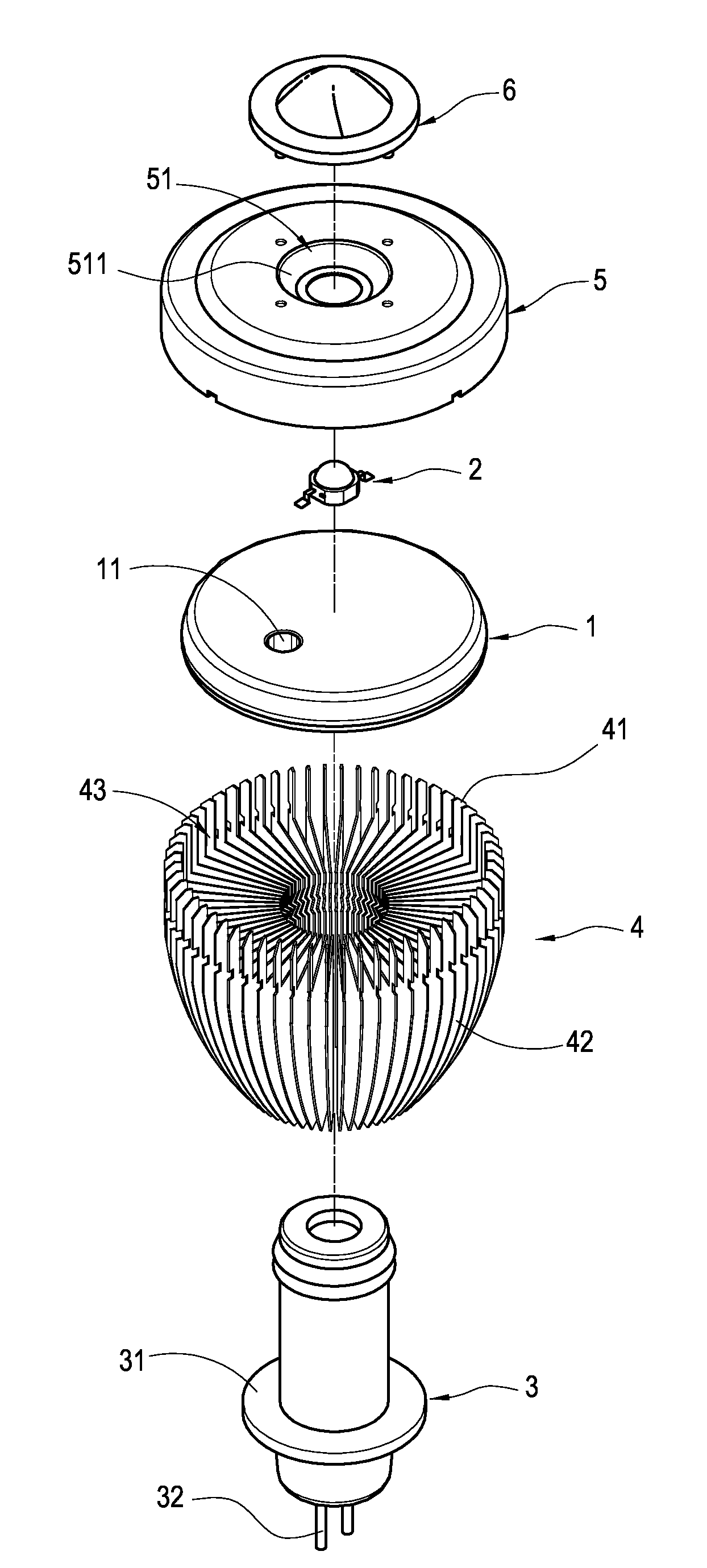
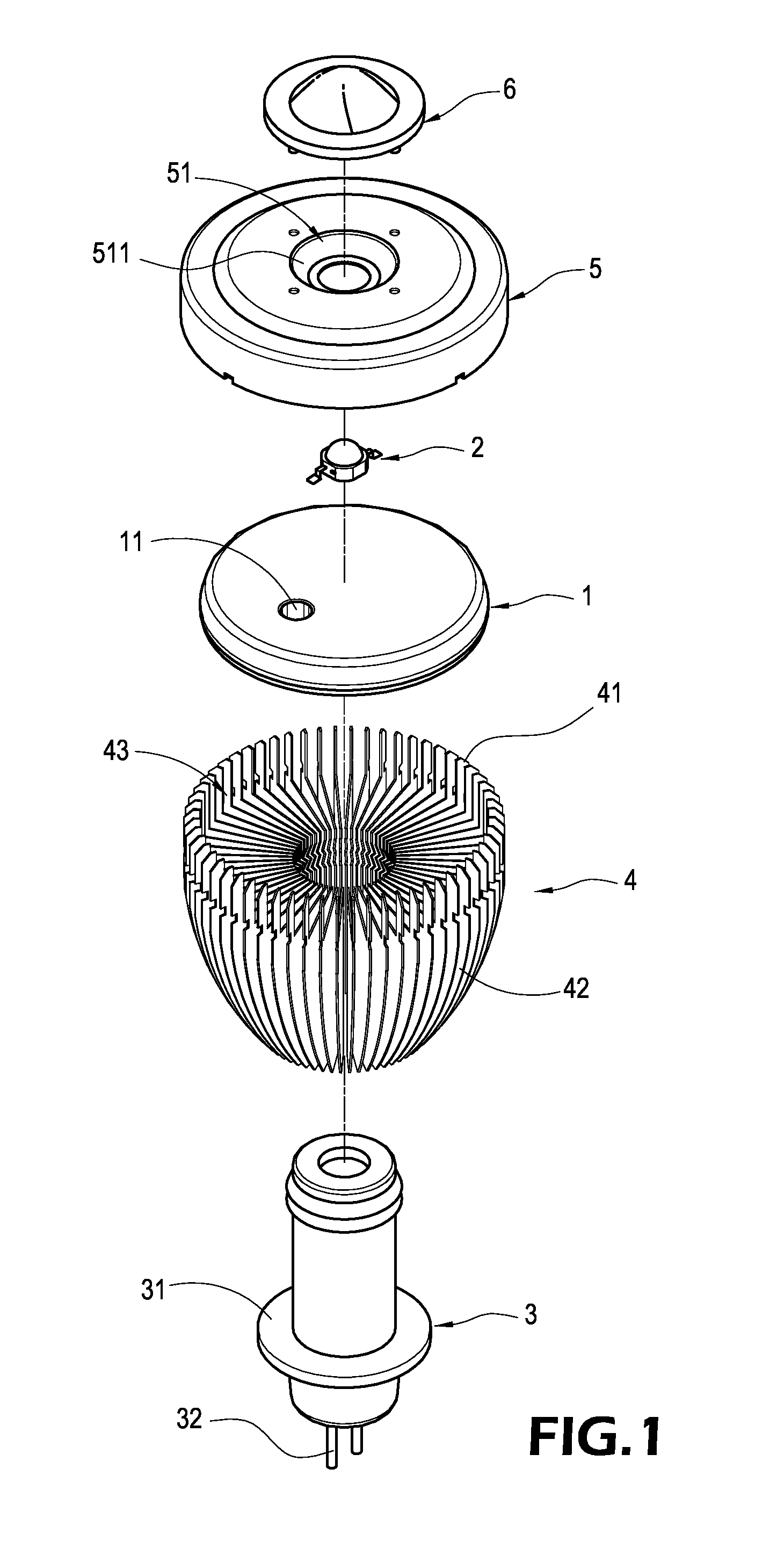
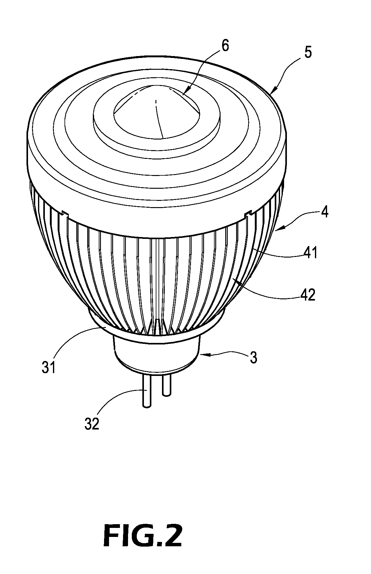
[0019]Referring to FIGS. 1 and 2 for a schematic view and a perspective view of the present invention, a signal lamp structure of the invention comprises an isothermal board 1, a light emitting element 2, a heat conducting cylinder 3, a heat dissipating body 4, a cover body 5, and a lid 6, wherein the isothermal board 1 of this embodiment is substantially in the shape of a circular disc, and the isothermal board 1 is made of a highly thermal conducting material. The isothermal board 1 has a through hole 11, and the light emitting unit 2 is disposed on the isothermal board 1, and the light emitting unit 1 of this embodiment is a light emit...


PUM


Abstract

A heat dissipating LED signal lamp emitting structure includes an isothermal board, a light emitting unit on the isothermal board, a heat conducting cylinder connected to the bottom of the isothermal board, a heat dissipating body around the periphery of the heat conducting cylinder and comprised of heat sinks, a circular cover body above the isothermal board for covering the isothermal board, a reflecting groove at the center of the cover body for passing through the light emitting unit, and a transparent lid on the cover body for covering the light emitting unit. With the heat dissipating effect of the heat dissipating body, the operating heat produced by the light emitting unit can be dissipated to the outside. The invention not only uses a single light emitting unit as a signal lamp emitting source, but also enhances the light emitting efficiency and the life expectancy of the light emitting unit.

Description

BACKGROUND OF THE INVENTION[0001]1. Field of the Invention[0002]The present invention relates to a signal lamp, and more particularly to a signal lamp structure that uses a light emitting diode as a light source.[0003]2. Description of Prior Art[0004]In general, a signal lamp is installed at an intersection of roads for directing pedestrians to walk or stop at a specific time, so as to assure the traffic flow and safety, maintain the order of traffics, and even lower the chance of traffic jams and accidents.[0005]A common traffic signal lamp is the three-color traffic signal lamp that reminds pedestrians when to walk or stop by means of three colors: red, yellow and green. A traditional three-color signal lamp uses white bulbs to work with red, yellow and green lens or color bulbs that can emit red, yellow and green lights, and the signal lamp is covered and protected by a lampshade, so as to form a light emitting structure of the signal lamp. However, the traditional signal lamp st...

Claims


Application Information

Patent Timeline
IPC IPC(8): F21V29/00
CPCF21V5/04F21V29/004F21Y2101/02F21V29/773F21K9/137F21V29/505F21V23/002F21K9/233F21Y2115/10
Inventor WANG, PEI-CHOA
Owner PYROSWIFT HOLDING CO LIMITED
Why Eureka
Try Eureka