Light Emitting Device
- Summary
- Abstract
- Description
- Claims
- Application Information
AI Technical Summary
Benefits of technology
Problems solved by technology
Method used
Image
Examples
first embodiment
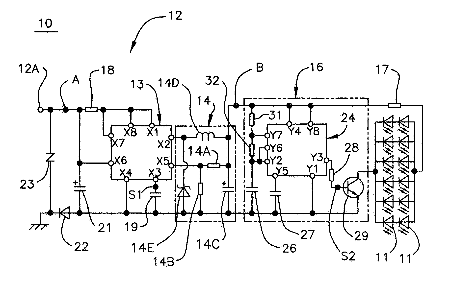
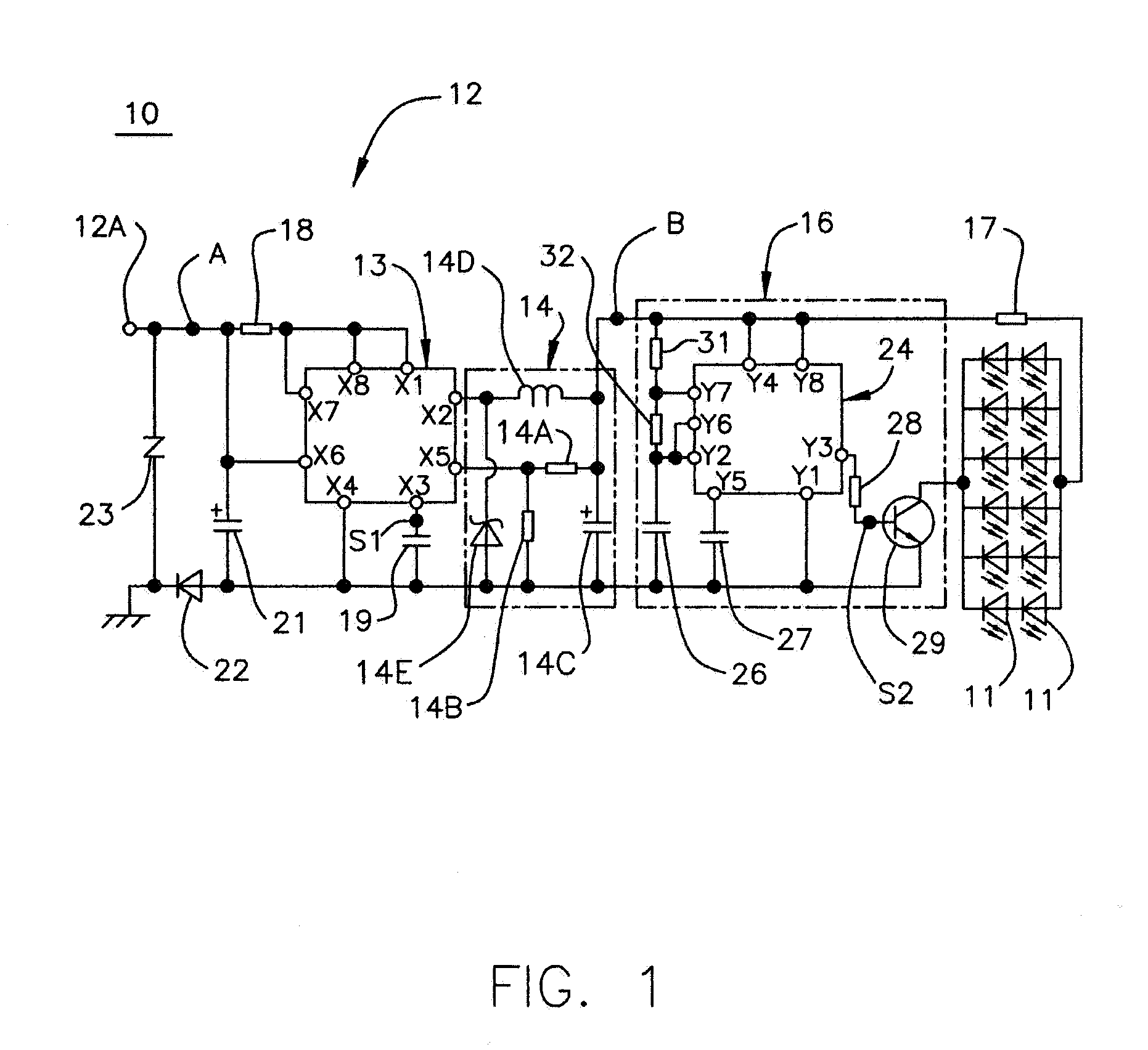
[0036] As shown in FIG. 1, a light emitting device 10 comprises twenty light emitting diodes 11 and a lighting circuit 12 for lighting these light emitting diodes 11. The twenty light emitting diodes 11 are configured so as to connect in parallel six sets of light emitting diodes 11, said sets each having two light emitting diodes connected in series. A high-power light emitting diode is used as each of these light emitting diodes 11. Concretely, there is used a light emitting diode having a forward current of 100 mA to 1000 mA, preferably 400 mA to 700 mA, a pulse forward current of 200 mA to 2000 mA, preferably 350 mA to 1000 mA, a allowable reverse current of 50 mA to 250 mA, preferably 80 mA to 150 mA, a power dissipation of 1.0 to 8.0 W, preferably 1.5 to 5 W, an operating temperature of −30 to 85° C., preferably −30 to 80° C., a storage temperature of −40 to 100° C., preferably 0 to 80° C., and a dice temperature of 80 to 160° C., preferably 80 to 120° C. (for example, LED of ...
example 1
[0047] As shown in FIG. 1, a light emitting device 10 was configured by connecting twelve light emitting diodes 11 to a lighting circuit 12. The twenty light emitting diodes 11 were connected so as to connect in parallel six sets of light emitting diodes, said sets each having two light emitting diodes connected in series. The resistance value of the first resistor 14a of the output control portion 14 was set at 7.5 kΩ, the resistance value of the second resistor 14b was set at 1.3 kΩ, and the resistance value of the limiting resistor 17 was set at 2.2Ω. The second heat-radiating member 42 to have the light emitting diode 11 mounted on it and the base member 43 to have the second heat-radiating member 42 mounted on it used ABS resin rather than a high thermal-conductivity resin (FIG. 5). This light emitting device 10 was determined as example 1.
example 2
[0048] A light emitting device was configured in the same way as example 1 except lighting by means of a lighting circuit ten light emitting diodes connected so as to connect in parallel five sets of light emitting diodes, said sets each having two light emitting diodes connected in series. This light emitting device was determined as example 2.
PUM
 Abstract
Description
Claims
Application Information
 - R&D
- Intellectual Property
- Life Sciences
- Materials
- Tech Scout
- Unparalleled Data Quality
- Higher Quality Content
- 60% Fewer Hallucinations
Browse by: Latest US Patents, China's latest patents, Technical Efficacy Thesaurus, Application Domain, Technology Topic, Popular Technical Reports.
© 2025 PatSnap. All rights reserved.Legal|Privacy policy|Modern Slavery Act Transparency Statement|Sitemap|About US| Contact US: help@patsnap.com


