Semiconductor memory and memory system

a technology of semiconductor memory and memory system, which is applied in the field of semiconductor memory, can solve the problems of long access cycle time, slow precharge operation, and no method of reducing the leak current accompanying the short circuit between a word line and a bit line in a shared sense amplifier type semiconductor memory. achieve the effect of reducing the leak current, preventing wasteful operation of the connection switch, and easy identification

Inactive Publication Date: 2008-02-14
SOCIONEXT INC
View PDF10 Cites 18 Cited by
  • Summary
  • Abstract
  • Description
  • Claims
  • Application Information

AI Technical Summary

Benefits of technology

[0010] An object of the present invention is to reduce a leak current accompanying a short circuit between a word line and a bit line in a shared sense amplifier type semiconductor memory. Another object of the present invention is to easily identify a bad memory block having a leak failure between a word line and a bit line.
[0011] In an embodiment of the present invention, a semiconductor memory has a pair of memory blocks, a sense amplifier shared by these memory blocks, and connection switches for connecting the sense amplifier to the bit lines of each memory block. Each memory block has a plurality of memory cells, and word lines and bit lines connected to the memory cells. Precharge switches connect the bit lines to a precharge line. A switch control circuit controls an operation of the precharge switch and sets a cutoff function to turn off the connection switch in a standby period in which no access operation of the memory cells is performed. Since connection between the bit lines and the precharge switch and that between the bit lines and the sense amplifier are cut off in the standby period, when a short circuit failure is present between a word line and a bit line, a leak current can be prevented from flowing from the word line to a precharge voltage line and the like.
[0012] In another preferred embodiment of the present invention, a semiconductor memory has a leak memory unit for storing information about a bad memory block having a leak failure between the word lines and bit lines. The cutoff function is set for a connection switch corresponding to a bad memory block and released for the connection switch corresponding to a good memory block without a leak failure based on information retained in the leak memory unit. By performing an operation of the connection switch involved in the cutoff setting only for bad memory blocks, wasteful operations of the connection switch can be prevented to reduce a standby current.
[0013] In another preferred embodiment of the present invention, the standby period is constituted by an external standby period in which external access requests and internal access requests can be received and an internal standby period in which reception of external access req

Problems solved by technology

However, when a resistor element is arranged between a precharge voltage line and a bit line or between a precharge voltage line and a sense amplifier, a precharge operation will be slower and an access cycle time longer as a resis

Method used


Image

  • Semiconductor memory and memory system
  • Semiconductor memory and memory system
  • Semiconductor memory and memory system

Examples


first embodiment

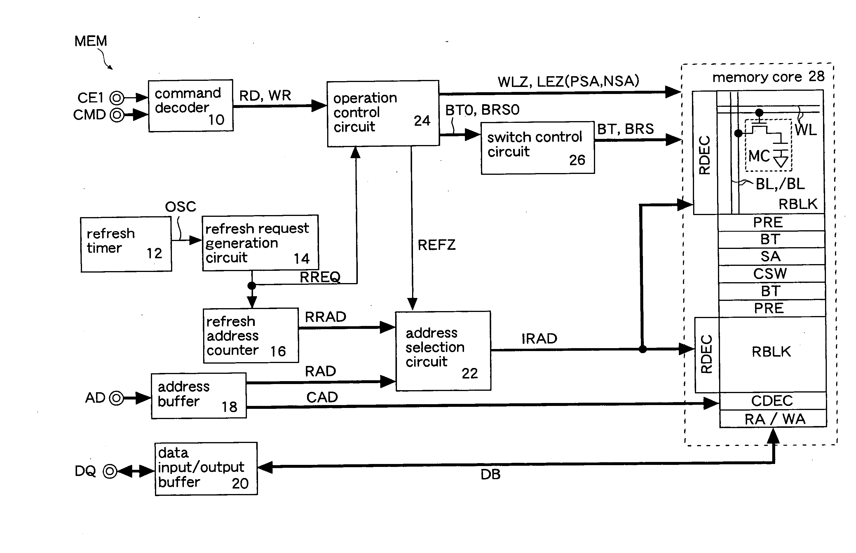
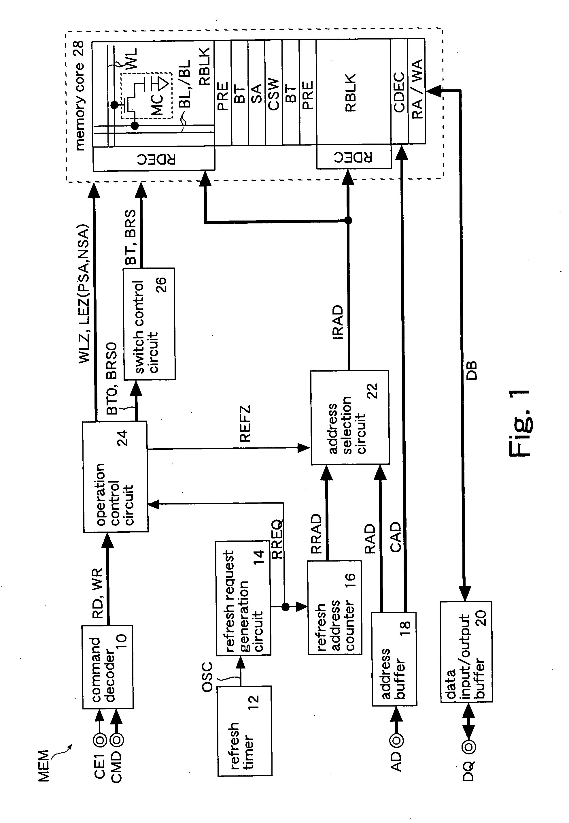
[0089]FIG. 1 shows the present invention. A semiconductor memory MEM is, for example, an FCRAM (Fast Cycle RAM). The FCRAM is a pseudo SRAM having memory cells of DRAM and an interface of SRAM. The memory MEM has a command decoder 10, a refresh timer 12, a refresh request generation circuit 14, a refresh address counter 16, an address buffer 18, a data input / output buffer 20, an address selection circuit 22, an operation control circuit 24, a switch control circuit 26, and a memory core 28. The memory MEM constitutes, as shown in FIG. 4 described later, a memory system together with a CPU.

[0090] The command decoder 10 outputs a command recognized in accordance with logical levels of a chip enable signal CE1 and a command signal CMD as a read command RD, a write command WR or the like for performing an access operation of the memory core 28. The read command RD and write command WR are external access requests for performing an access operation to the memory core 28. For example, the...

fourth embodiment

[0134] Other components are the same as those in the

[0135] The switch control circuit 26E sets the cutoff function for the bad memory blocks RBLK0 and 2 only in the self-refresh period SREFP (internal standby period) in which the chip enable signal CE1 is inactivated. The switch control circuit 26E releases the cutoff function for good memory blocks RBLK and also releases the cutoff function in an activation period ACTP (external standby period) in which the chip enable signal CE1 is activated.

[0136]FIG. 14 shows operations of the sixth embodiment. Locations of bad memory blocks RBLK and the sequence of access operations RD, WR, and SREF are the same as those in the first embodiment. A detailed description of the same operation as that in the first embodiment is omitted. The operation in the activation period ACTP is the same as that in the fourth embodiment (FIG. 11).

[0137] In the present embodiment, when a self-refresh operation SREF is performed in the bad memory block RBLK2, t...

sixth embodiment

[0138] Also in the sixth embodiment described above, the same advantages as those of the above embodiments can be obtained. Further, in the present embodiment, a precharge operation of the bit lines BL and / BL can be performed for each refresh request RREQ in all bad memory blocks RBLK0 and 2 by releasing the cutoff function for all bad memory blocks RBLK0 and 2 for each refresh request RREQ. This can minimize a shift of the bit lines BL and / BL in the self-refresh period SREFP.

[0139]FIG. 15 shows operations of a seventh embodiment. The same symbols and numerals are attached to the same components as those described in the above embodiments and a detailed description thereof is omitted. In the present embodiment, the cutoff function to turn off the connection switch BT is set in a period in which no access operation RD or WR is performed in the activation period ACTP. Other components are the same as those in the sixth embodiment (FIG. 14). A memory MEM in the present embodiment is ...


PUM


Abstract

Each memory block has a plurality of memory cells, and word lines and bit lines connected to the memory cells. Precharge switches connect the bit lines to a precharge line. A switch control circuit controls an operation of the precharge switches and sets a cutoff function that turns off connection switches in a standby period in which no access operation of the memory cells is performed. Since connections of the bit lines and the precharge switch and those of the bit lines and the sense amplifier are cut off in the standby period, if a short circuit failure is present between a word line and a bit line, a leak current can be prevented from flowing from the word line to a precharge voltage line and so on.

Description

CROSS REFERENCE TO RELATED APPLICATION [0001] This application is based upon and claims the benefit of priority from Japanese Patent Application No. 2006-218658, filed on Aug. 10, 2006 and Japanese Patent Application No. 2007-147347, filed on Jun. 1, 2007 the entire contents of which are incorporated herein by reference. BACKGROUND [0002] 1. Field [0003] The present invention relates to a semiconductor memory having memory cells and a memory system having the semiconductor memory and a controller. [0004] 2. Description of the Related Art [0005] In a semiconductor memory such as a DRAM, a memory cell is connected to one of a pair of complementary bit lines via a transfer gate operating in accordance with a voltage of a word line. In a read operation, data retained in the memory cell is output to one of the pair of bit lines. The other of the bit lines is set to a precharge voltage before the read operation. Then, a voltage difference between the pair of bit lines is amplified by a se...

Claims


Application Information

Patent Timeline
IPC IPC(8): G11C7/00
CPCG11C7/12G11C2211/4067G11C8/06G11C8/10G11C8/12G11C11/401G11C11/406G11C11/40615G11C11/4072G11C11/4087G11C11/4094G11C29/50G11C2029/5006G11C2207/2227G11C7/20G11C11/4074G11C11/4091
Inventor KOBAYASHI, HIROYUKI
Owner SOCIONEXT INC
Why Eureka
Try Eureka