Combustion Apparatus for Solid Fuel

a technology of combustion apparatus and solid fuel, which is applied in the direction of lighting and heating apparatus, domestic stoves or ranges, heating types, etc., can solve the problems of consumable devices, wear and tear of coatings that act as catalysts, and inefficient conventional solid fuel burning apparatus, etc., to reduce emissions and shorten the effect of venting structure and alternative rou

Inactive Publication Date: 2008-02-21
BROWN STEPHEN CHARLES
View PDF51 Cites 26 Cited by
  • Summary
  • Abstract
  • Description
  • Claims
  • Application Information

AI Technical Summary

Benefits of technology

[0018] Further advantageously, the additional air washes upwards over a glass door, cleaning the glass and providing primary and secondary air for combustion. A catalytic reaction may be initiated furthest downstream, preferably in the SCZ, to further reduce emissions. The exhaust may be vented via a stack including a coaxial sheath, where the stack projects from the rear of the stove at an angle greater than 10 degrees above the horizontal.
[0019] Finally, rear and top direct vented variations of the combustion apparatus are provided whereby at least two coaxially mounted stove pipes are provided to vent exhaust via an inner pipe and provide air from outside a building envelope via an outer pipe, thereby permitting relatively short and alternatively routed venting structures.

Problems solved by technology

Conventional solid fuel burning apparatus are extremely inefficient because a substantial portion of the solid fuel's combustible energy is sent up the stack in the form of creosote, oils, tars, heavy combustible gases and smoke (pollution).
Prior art such as “Advanced Techniques for Wood Log Combustion Emission Comparisons”, by Øyvind Skreiberg of the Norwegian Institute of Technology, Institute of Thermal Energy and Hydro Power, disclosed at Comett Expert Workshop, “Biomass Combustion”, May 1994) discloses that catalytic converters, however, can lead to an increase in NOX emissions.
One further disadvantage of catalytic converters is that they are a consumable device—the coating that acts as the catalyst wears off with use.
However, through experimentation, it has been found that horizontally fed air is not the most efficient way of establishing a turbulent air environment.
The '762 patent also suffers from the disadvantage of requiring a calibration procedure to adjust the flow of the secondary air supply ducts at the time of installation.
This is impractical because each fuel source (i.e. different types of wood or coal) combusts differently, so the apparatus of '762 requires calibration every time a different fuel is used.
Patent '801 relies on a catalytic converter between the second and third combustion chambers for complete combustion of the fuel; the disadvantage of this has been discussed above.
Further, in practice, the top-down air (counter-acting airflows) results in a build up of combustion products at the bottom of the window, thereby requiring the user to constantly clean the window and thereby defeating the purpose of the air wash.
Also, as explained hereinabove, the use of a top-down air wash does not work well in practice.
The disadvantage of using a catalytic converter has been discussed hereinabove.
This vertical height restriction severely limits the type of building in which solid fuel apparatus may be used due to space and design constraints.

Method used


Image

  • Combustion Apparatus for Solid Fuel
  • Combustion Apparatus for Solid Fuel
  • Combustion Apparatus for Solid Fuel

Examples


Embodiment Construction

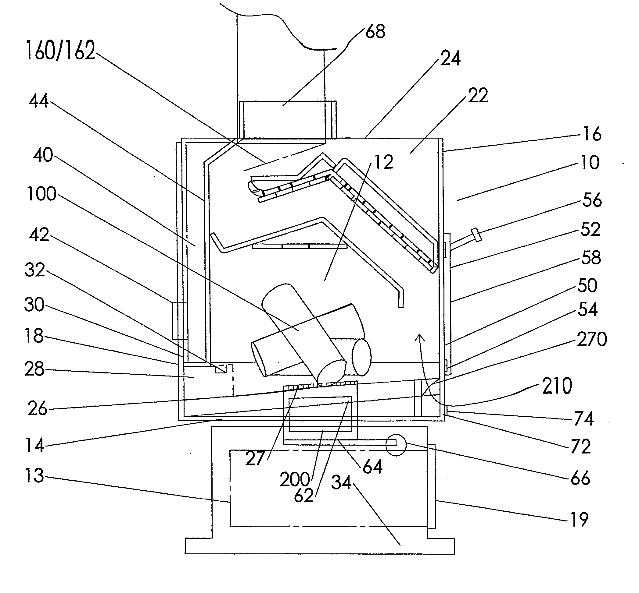
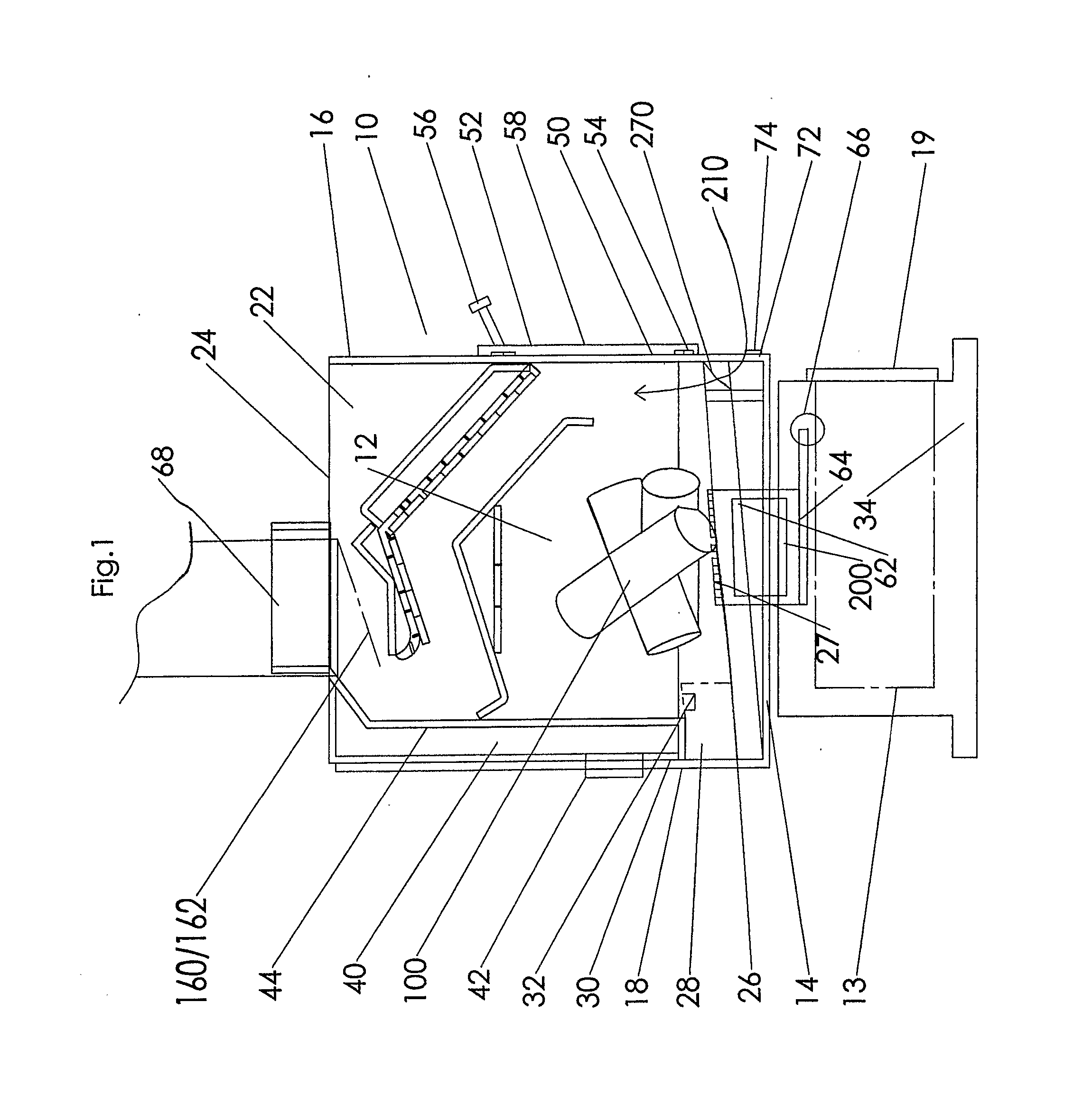
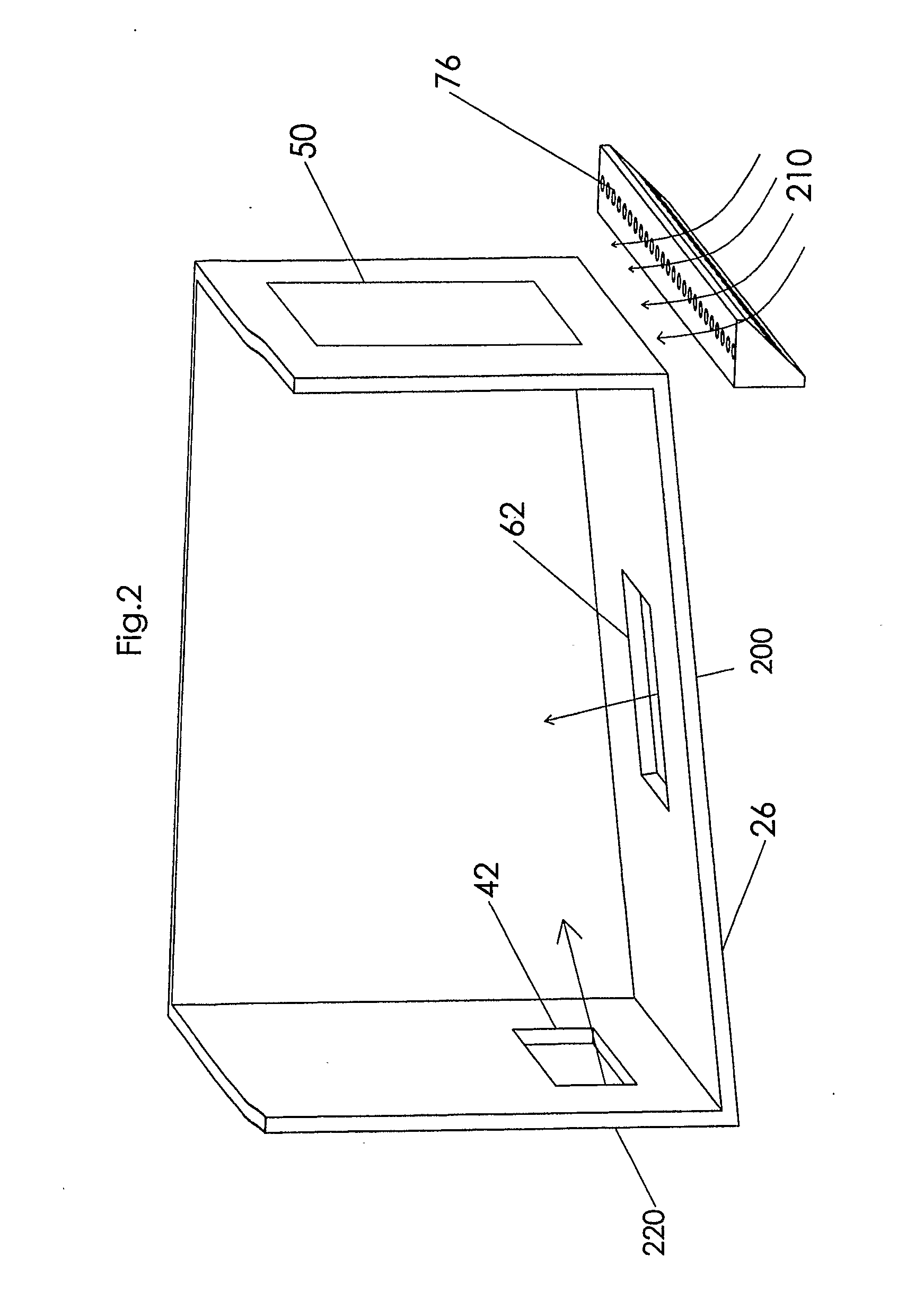
[0032] Referring to FIG. 1, the preferred embodiment of the invention, a natural draft secondary combustion apparatus 10 is shown in perspective. The combustion apparatus 10 includes a firebox 12, which is generally cube or box shaped and comprised of six planar panels, each having four edges contiguous with the edges of four other panels. The panels, specifically a bottom 14, front wall 16, back wall 18, left wall 20, right wall 22 and top wall 24 form the firebox 12. The front wall 16, left wall 20, right wall 22 and back wall 18 extend vertically from the bottom 14 and are capped by the top wall 24. The left wall 20 and right wall 22 extend between the front wall 16 and back wall 18. The firebox 12 is supported by a pedestal / base 34. The pedestal / base 34 has a front opening door 19 provides access to an ash drawer 13. The firebox 12 preferably has a 127 mm (5″) round flue exit collar 68 situated in the back half region of top wall 24. The flue collar 68 may also be 15 mm or 6″ in...


PUM


Abstract

A combustion apparatus for the burning of solid fuel using a plurality of secondary combustion zones is disclosed. The combustion apparatus includes primary and secondary air inlets, an inclined hearth and a unique second air source which washes up a window in the combustion apparatus creating a floating flame effect and rendering the window self-cleaning. A series of baffles define a secondary combustion pathway which optimizes secondary combustion of exhaust gasses and particulate matter. Coaxial rear and top direct venting apparatus are also disclosed. The combustion apparatus provided combusts a wide range of solid fuel at a high level of efficiency.

Description

TECHNICAL FIELD [0001] The present disclosure relates to a secondary combustion apparatus for the burning of solid fuel such as cord wood, coal or wood pellets. More specifically, the disclosure relates to a method and apparatus for burning solid fuel which a enables much greater degree and effectiveness of secondary combustion of volatile combustion products, thereby dramatically reducing smoke emission and greatly improving efficiency. BACKGROUND OF THE INVENTION [0002] It is well known in the art that a substantial portion of the emissions generated by a solid fuel combustion apparatus are themselves combustible. Conventional solid fuel burning apparatus are extremely inefficient because a substantial portion of the solid fuel's combustible energy is sent up the stack in the form of creosote, oils, tars, heavy combustible gases and smoke (pollution). Therefore, by ensuring more complete combustion of these emissions, the efficiency of the combustion apparatus is greatly improved ...

Claims


Application Information

Patent Timeline
Patent Type & Authority Applications(United States)
IPC IPC(8): F24B1/02F23L9/02F23L15/00F23L15/04F23M3/14F23M9/04F23M9/06F24B5/02F24B13/02
CPCF23L9/02F23L15/00F23L15/04F24B5/028F23M9/06F24B5/026F23M9/04F24B1/006Y02E20/34
Inventor BROWN, STEPHEN CHARLES
Owner BROWN STEPHEN CHARLES
Why Eureka
Try Eureka