[0012]One
advantage of the present motorized pump assembly is its reduced
noise level. Although the motorized high pressure pump produces hydraulic pressures of about 2,000 to 10,000 psi or more at flow rates of 4 to 18 gpm or more, the
noise level of the assembly at a distance of three feet from the unit is kept to about 75 to 77 decibels or less. This
noise reduction is a result of reduced vibration and the use and arrangement of noise absorbing sheets placed in the windows of the frame segments. The thin, plastic, sound absorbing sheets have a porous surface that dampens noise. The sheets are sonically welded to the inside surface of the plastic housing. The sheets are folded to form a box shape. The sheets have a flat main portion that is spaced from the housing to form a dead zone of air between the sheet and the housing. The sheets and dead zones are compactly arranged to fit within the windows of the frame segment. A bottom sheet is also located along the bottom of the frame. The motor intake air vent and the exhaust vent at the top of the frame include noise insulation and baffles. The dramatic reduction in noise of the present motorized pump assembly meets the
noise level requirements for machinery and equipment used in many
industrial setting such as Ford Motor Company manufacturing plants.
[0013]Another
advantage of the present motorized pump assembly is vibration suppression.
High pressure pumps generate large pulses of energy and vibrations. The
drive motor also generates vibrations. The structure of the frame inhibits the transmission and multiplication or excitement of these vibrations. The frame is composed of upper and lower portions. The upper portion is formed by frame members with different cross sectional sizes than the lower portion. The frame is also formed by several frame segments. These segments have different shapes and sizes, and do not form a square. The platforms on which the motor and pump are mounted are also constructed differently and include plates having different thicknesses. This construction produces frame segments and parts with different natural frequencies that inhibit the multiplication or excitement of vibrations. The construction also helps attenuate and minimize the propagation of the motor and pump vibrations through the frame. The shafts of the motor and pump are also offset from the center of the housing, and flex hose and shock absorbing rubber mounting pads are used to reduce vibration excitement and propagation. This vibration suppression reduces the
wear and tear on the frame, housing and internal components attached to the frame. The reduced vibration also reduces the noise level of the overall assembly.
[0014]A still further
advantage of the present motorized pump assembly is the
visibility and lighting of its active internal components. Good
visibility and lighting are particularly important because
external noise is below 77 decibels, while the
background noise of many manufacturing settings is typically about or above 80 decibels. As a result, workers cannot hear component noises inside the acoustic frame and housing assembly that would otherwise
signal a need for maintenance or an impending malfunction, such as a
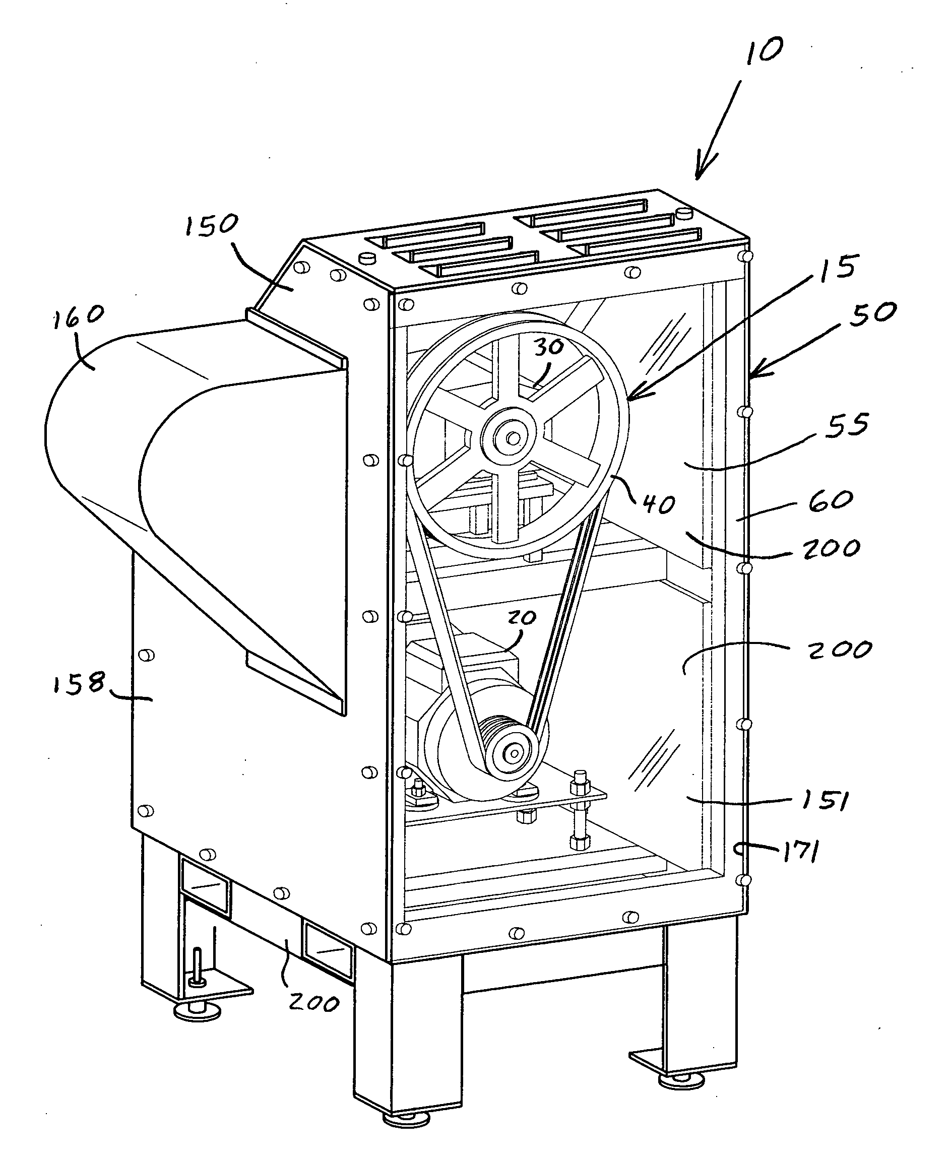
high pitched whir of a worn drive belt. Although the frame and housing assembly surround the internal components, two panels are transparent plastic to provide windows for viewing those components. The windows are located on the front and rear of the assembly. This opposed, dual window design allows light to enter the opposite side from the
line of sight of the viewer to provide backlighting for each window. A worker can view the internal components through either window without shadowing that can hide or hinder the observation of
smoke, leaks, belt deterioration or loosening, excessive vibration, or other sometimes difficult to detect abnormalities. The accumulation of belt flakes or leaking fluid at the bottom of the housing is easily seen through the front window, which spans from the bottom to the top of the assembly, and which is located directly in front of and provides unobstructed viewing of the
pulley and drive belt assembly. The rear window is located directly behind and allows for unobstructed viewing of the pump and motor. The rear window is angled relative to the vertical front window. This angled arrangement inhibits the
reverberation of noise between the windows, and provide a clear view of both the pump and motor, which are stacked one on top the other. The dual window design utilizes ambient room light and avoids the problems of providing and maintaining a fixed internal
light source, which can also produce a shadowing effect. The ergonomic design also allows workers to properly inspect the internal components without bending over, kneeling down or contorting their body into an unnatural position. As a result, the expensive, high speed equipment can be routinely inspected to ensure their proper operation.
[0015]A still further advantage of the present motorized pump assembly is its ventilation. Both the pump and motor are adequately ventilated and cooled by room air so that they do not overheat. The high power
electric motor and the pump are kept within design specifications during operation. The air vent openings in the housing include baffles to abate the transmission of noise, and are located where they do not obstruct
visibility through the front and angled rear windows.
[0017]A further advantage of the present motorized pump assembly is its compact size, which is achieved by a number of design features. First, the pump and motor have a stacked arrangement. The pump is located above the motor. Second, only active high speed components such as the pump, motor and
pulley drive are enclosed in housing of the assembly. Static components such as tanks and control panels that do not require vibration and
noise control are positioned outside the frame and housing. Third, the noise absorbing sheets are thin and effective. Bulky masses of insulation are not used. Fourth the noise absorbing sheets are located inside the openings or windows of the frame segments so that they do not increase in the overall size of the assembly. The surface area of the noise insulation actually exceeds the surface area of the
interior space of the assembly. Thus, the overall assembly has a
small footprint and conserves manufacturing floor space. The compact size also reduces the cost of enclosing the motorized pump in an acoustic housing.
[0018]A still further advantage of the present motorized pump assembly is its ergonomic design and ease of maintenance. By elevating the frame, workers can more easily perform routine maintenance such as oil changes, applying lubricants, filter cleaning or replacement, bolt tightening, hose replacement, etc. A small access opening is provided in the rear window so that a worker can check the oil level without removing any housing panels. The opening is located directly above the oil dip stick and allows the worker to see his or her hand and the dip stick as they reach into the housing. Workers do not need to bend over or work off the floor. The elevated design also allows
dirt and debris to be easily cleaned away from the floor and around the unit, even during operation.


