
Air pollutants reduction system

a technology of air pollutants and reduction systems, applied in the field of air pollutants reduction systems, can solve the problems of reducing carbon dioxide, generating huge amount of air pollutants into the atmosphere, and limited amount of carbon dioxide absorbed and converted per plant, so as to reduce the actual amount of air pollutants, reduce maintenance costs, and reduce the effect of carbon dioxide discharg

Inactive Publication Date: 2008-02-21
VITABIO
View PDF2 Cites 12 Cited by
  • Summary
  • Abstract
  • Description
  • Claims
  • Application Information

AI Technical Summary

Benefits of technology

The present invention is an air pollutants reduction system that uses photosynthesis and biological activities to convert air pollutants into nutrients, hydrocarbon materials, and oxygen. This system can efficiently reduce carbon dioxide discharge from combustion exhaust for industrial applications and is energy efficient, trouble-free to operate, and cost-effective. Additionally, it can produce commercial by-products to cover the operation cost.

Problems solved by technology

The addition to use carbon-based fuels as the fundamental energy source keeps generating huge amount of air pollutants into atmosphere.
In carbon-based fuel burning process, its chemical reaction generates carbon dioxide and may generate other unwanted products such as carbon monoxide, SOx, NOx, and other pollution materials.
The amount of carbon dioxide absorbed and converted is limited per plant due to the conditions from its presented environment.
The plant tender mainly can reduce carbon dioxide indoors with limited amount of capacity and is not capable to take care other polluting materials such as carbon monoxide, sulfur oxide, and nitrogen oxide.
However, the intensity of light did not considered for providing efficient photosynthesis.

Method used


Image

  • Air pollutants reduction system
  • Air pollutants reduction system

Examples


Embodiment Construction

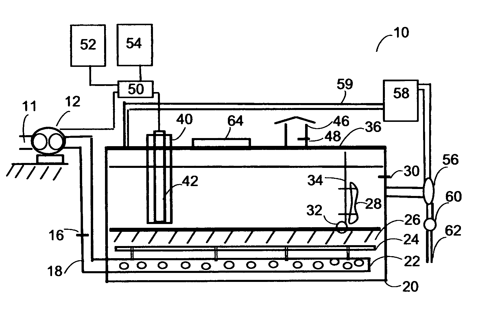
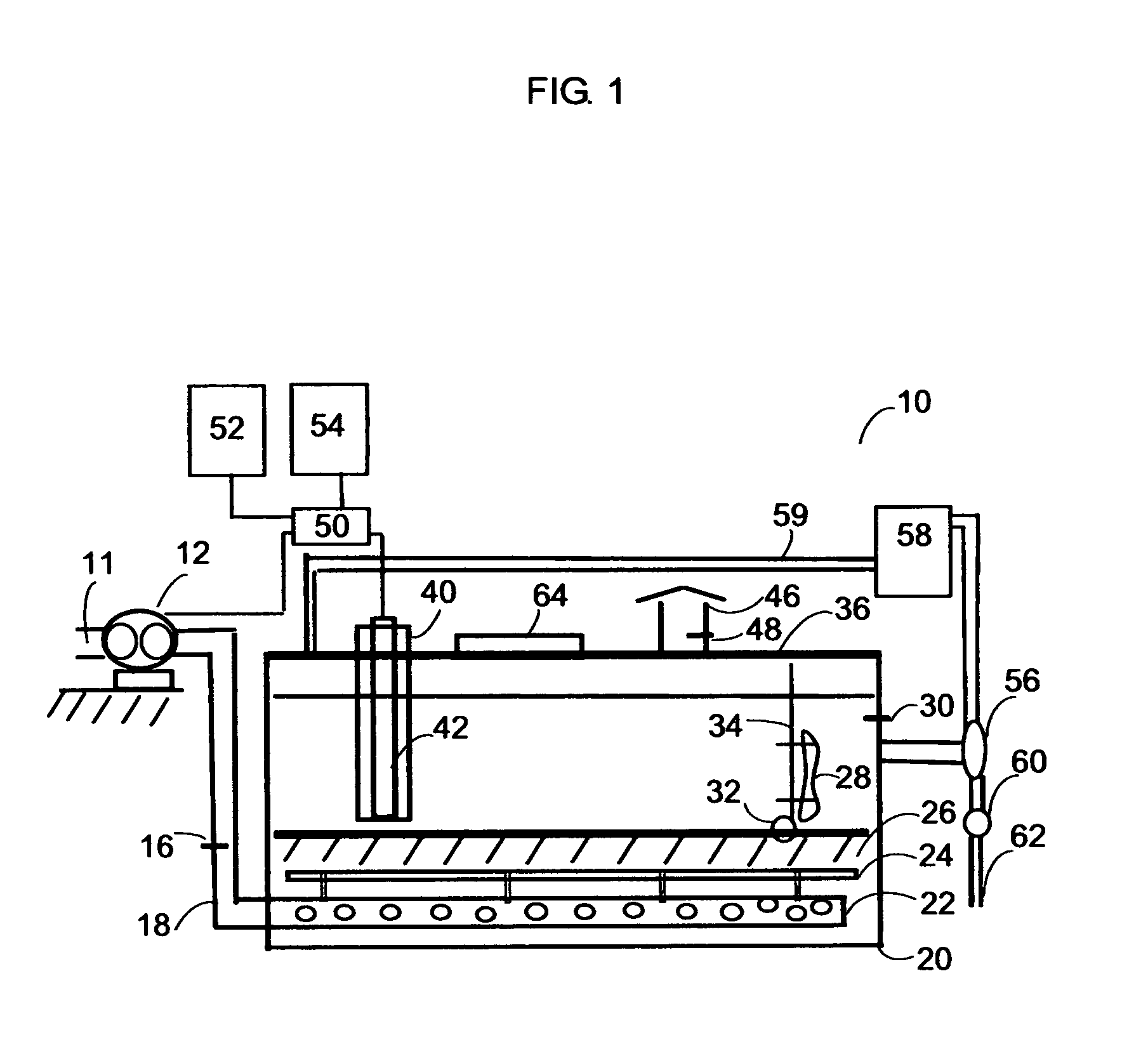
[0017]A preferred embodiment of the air pollutants reduction system is illustrated in a schematic diagram in FIG.1 and is referred to by the general reference character 10. In this illustration it may be seen that the air pollutants reduction system 10 is adapted to receive inflow of mixture of air pollutants 11 that containing the carbon monoxide, carbon dioxide, partially burned carbon gases and solid particles, NOx, SOx, odors and air, through blower 12.

[0018]Blower 12 delivers mixture of air pollutants 11 through air pipe 18 into tank 20. A sensor device 16 is used to analyze the compositions of mixture of air pollutants 11. Tank 20 can be in a cylindrical shape, a rectangular shape, or other shapes to fit into the operation requirements. Furthermore, tank 20 can be made of transparent material to allowing light passing through. A perforated pipe 22 connects with air pipe 18 to distribute mixture of air pollutants 11 inside the lower portion of tank 20. Perforated pipe 22 can be...


PUM

PropertyMeasurementUnit
temperatureaaaaaaaaaa
distanceaaaaaaaaaa

Abstract

Disclosed herein is a method for the air pollutants reduction system. The method comprises the reduction of air pollutants from their generated source, and biologically converting them into other forms of hydrocarbon materials and oxygen with the disclosed process.

Description

FIELD OF INVENTION[0001]This invention related generally to processes and systems for use in the reduction of air pollutants from burning solid, liquid, and gas fuels, and more specifically related to a method and system for use in the reduction of air pollutants by the combined photosynthesis and ecological process in a disclosed system.BACKGROUND OF INVENTION[0002]The present invention is directed to the emission reduction of exhaust from fuel burning, and in particular to biologically convert more than one component of air pollutants that include carbon dioxide, carbon monoxide, partially burned carbon based gases, nitrogen oxide including nitrogen monoxide and nitrogen dioxide, commonly referred to as NOx, sulfur oxide including sulfur monoxide and sulfur dioxide, commonly referred to as SOx, odors and air. As such, the present invention is directed to the air pollutants reduction, for example, electric power plant that burning fuels, municipal incinerator, Industrial or commerc...

Claims


Application Information

Patent Timeline
Patent Type & Authority Applications(United States)
IPC IPC(8): C12M1/00
CPCB01D53/84Y02A50/20
Inventor WU, ARTHUR C.
Owner VITABIO
Learn More