Blood Processing Apparatus with Robust Automated Process Control

a blood processing apparatus and process control technology, applied in separation processes, centrifuges, image enhancement, etc., can solve the problems of significant control problems of the interface between blood components, and the response to changes in intensity in the flux monitoring region is not fast enough to maintain the quality of blood product being collected, so as to reduce the detection of false phase boundaries

Active Publication Date: 2008-02-21
CARIDIANBCT
View PDF23 Cites 28 Cited by
  • Summary
  • Abstract
  • Description
  • Claims
  • Application Information

AI Technical Summary

Benefits of technology

[0013]Collect port measuring of intensity in the flux monitoring region allows measurement of cellular material leaving through the collect port in real time. Statistical measures may be used for such parameters as the hematocrit of collected blood product, allowing for more accurate collection of a desired type of product.
[0015]It is also an object of the invention to provide a monitoring system for a density centrifuge blood processing system for separating fluid components having computational apparatus receiving intensities for selected pixels and determining a diffusion function to reduce detection of false phase boundaries between blood components. Another object is having a diffusion function comprising second partial derivatives of the intensity in at least two directions and a partial derivative of intensity with respect to time. Also, the diffusion function may compute the intensity of a pixel by computingIt+1=It+α*(Iij−1+Ui+1j+Ii+1j+Iij+1−4*Iij)Where α is an empirical constant;

Problems solved by technology

In a high-speed centrifuge for separating blood components, control of the interface between blood components presents significant control problems.
Responding to changes in intensity in the flux monitoring region would not be rapid enough to maintain the quality of blood product being collected.

Method used


Image

  • Blood Processing Apparatus with Robust Automated Process Control
  • Blood Processing Apparatus with Robust Automated Process Control
  • Blood Processing Apparatus with Robust Automated Process Control

Examples


Embodiment Construction

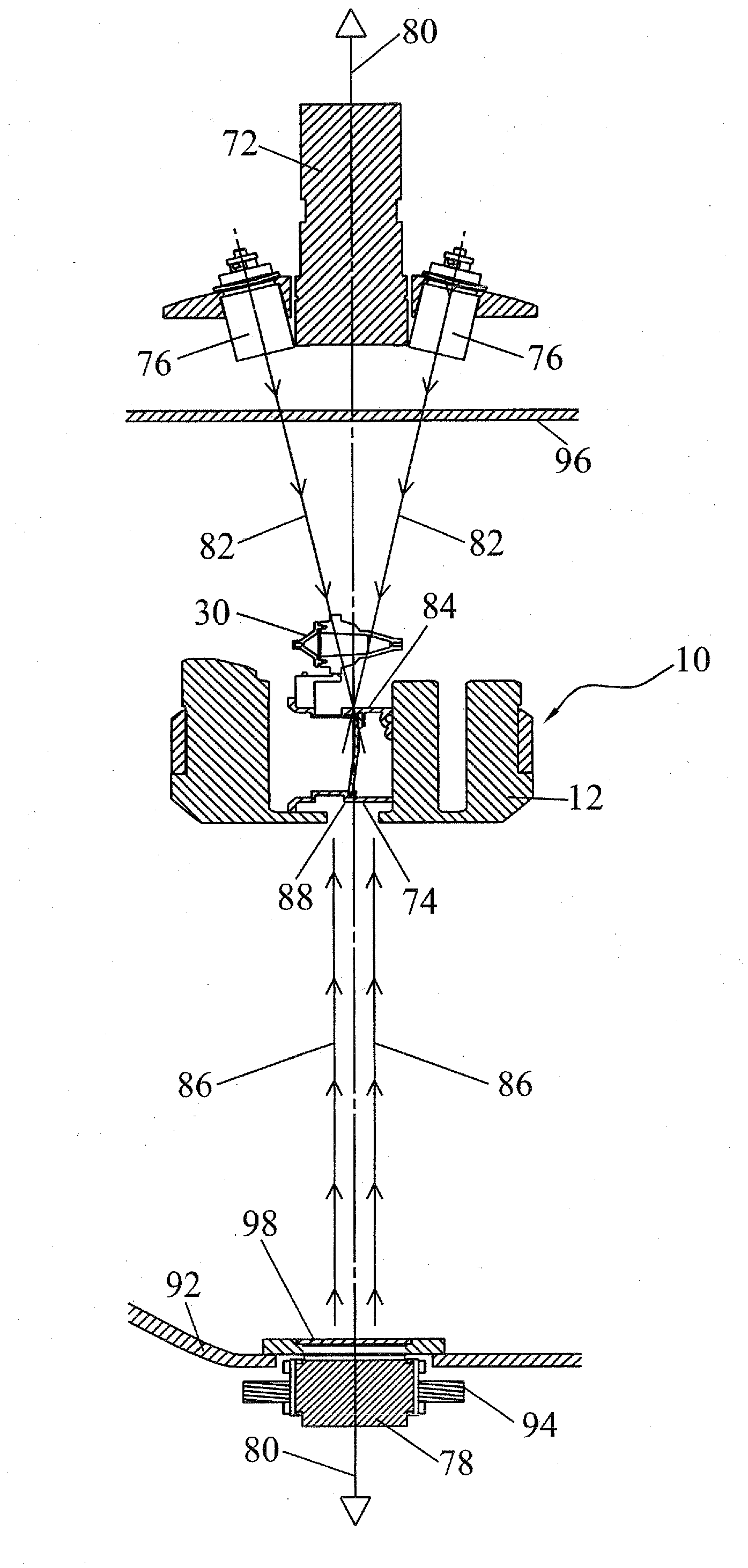
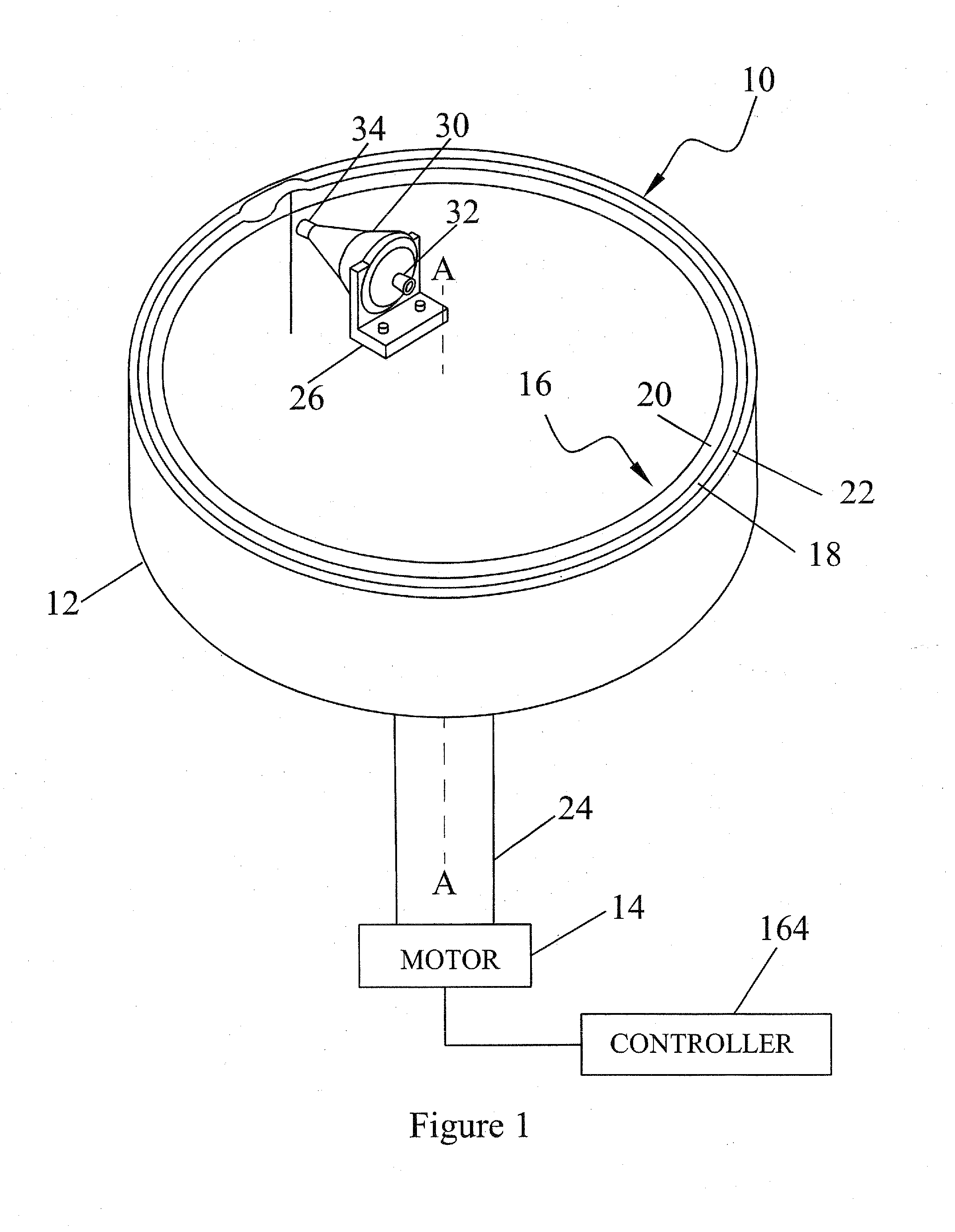
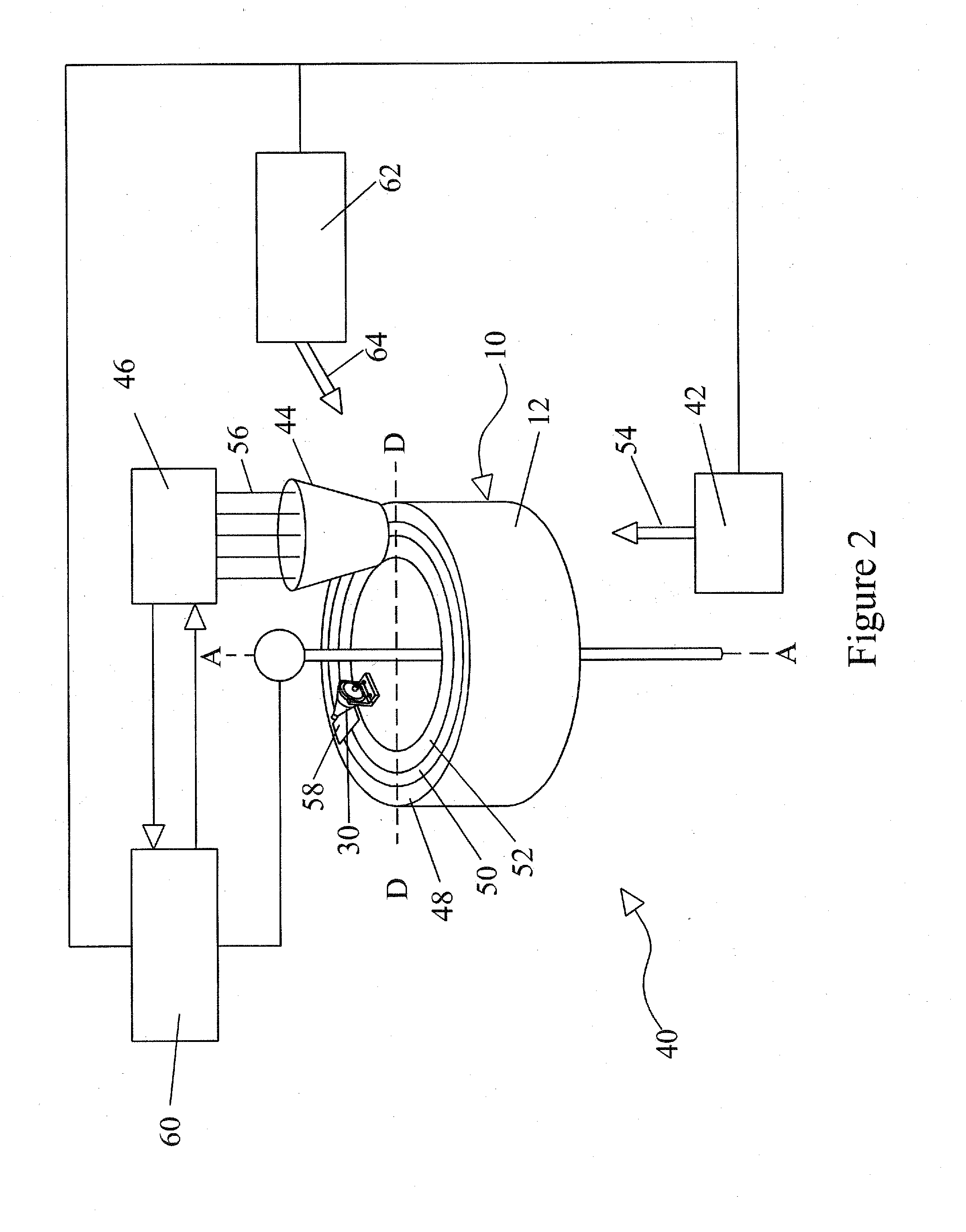
[0039]The present invention preferably comprises a blood processing apparatus having a camera control system, as disclosed in U.S. patent application Ser. Nos. 10 / 884,877 and 10 / 905,353. It may also be practiced with a TRIMA® blood component centrifuge manufactured by Gambro BCT, Inc. of Colorado or, alternatively, with a COBE® SPECTRA™ single-stage blood component centrifuge also manufactured by Gambro BCT, Inc. Both the TRIMA® and the SPECTRA™ centrifuges incorporate a one-omega / two-omega sealless tubing connection as disclosed in U.S. Pat. No. 4,425,112 to Ito. The SPECTRA™ centrifuge also uses a single-stage blood component separation channel substantially as disclosed in U.S. Pat. No. 4,094,461 to Kellogg et al. and U.S. Pat. No. 4,647,279 to Mulzet et al. The invention could also be practiced with a TRIMA® or TRIMA ACCEL® centrifugal separation system or other types of centrifugal separator. The method of the invention is described in connection with the aforementioned blood p...


PUM

PropertyMeasurementUnit
densityaaaaaaaaaa
processingaaaaaaaaaa
speedaaaaaaaaaa

Abstract

A centrifuge for separating blood having a camera observing fluid flow, and a controller controlling the flow. The location of an interface is detected by image processing steps, which may comprise the steps of “spoiling” the image, “diffusing” the image, “edge detection”, “edge linking”, “region-based confirmation”, and “interface calculation”. “Spoiling” reduces the number of pixels to be examined preferentially on orthogonal axis oriented with respect to the expected location of the interface or phase boundary. “Diffusing” smoothes out small oscillations in the interface boundary, making the location of the interface more distinct. “Edge detection” computes the rate of change in pixel intensity, or. “Edge linking” connects adjacent maxima. “Region-based confirmation” creates a pseudo image of the regions that qualify as distinct. “Final edge calculation” uses the points where the shade changes in the pseudo image, averages the radial displacement of these points for the interface position.

Description

CROSS REFERENCE TO RELATED APPLICATIONS[0001]This application claims the benefit of U.S. Provisional Application No. 60 / 822,672 filed Aug. 17, 2006.FIELD OF THE INVENTION[0002]The present invention relates to an apparatus and method for separating particles or components of a fluid. The invention has particular advantages in connection with separating blood components, such as white blood cells and platelets.[0003]This application is related to U.S. Pat. No. 5,722,926, issued Mar. 3, 1998; U.S. Pat. No. 5,951,877, issued Sep. 14, 1999; U.S. Pat. No. 6,053,856, issued Apr. 25, 2000; U.S. Pat. No. 6,334,842, issued Jan. 1, 2002; U.S. patent application Ser. No. 10 / 884,877 filed Jul. 1, 2004; U.S. patent application Ser. No. 10 / 905,353, filed Dec. 29, 2004; and U.S. patent application Ser. No. 11 / 163,969, filed Nov. 4, 2005.DESCRIPTION OF THE RELATED ART[0004]In the medical field, it is often necessary to separate blood into components. Whole blood consists of various liquid components...

Claims


Application Information

Patent Timeline
Patent Type & Authority Applications(United States)
IPC IPC(8): B04B13/00B01D21/26G01N33/487
CPCB04B5/0442B04B13/00B04B2013/006G01N15/042G01N15/05G01N33/491H04N7/18G06T7/0083G06T2207/10016G06T2207/20068G06T2207/20136G06T2207/30024B04B15/00G06T7/0012G06T7/12G06T7/181
Inventor KOLENBRANDER, JEREMYDALVI, ADITYAFLETCHER, CHRISTOPHERSWEAT, WILLIAMLINDNER, JOHN R.
Owner CARIDIANBCT
Why Eureka
Try Eureka