Diagnostic methods for electrical cables utilizing axial tomography

a technology of axial tomography and diagnostic methods, applied in the direction of fault location by conductor type, line-transmission details, instruments, etc., can solve the problems of affecting the and affecting the quality of electrical cables. , to achieve the effect of convenient identification and location of defects

Active Publication Date: 2008-02-28
INSTR MFG
View PDF9 Cites 65 Cited by
  • Summary
  • Abstract
  • Description
  • Claims
  • Application Information

AI Technical Summary

Benefits of technology

[0020]The present disclosure is directed to cable diagnostic test methods, systems and apparatus that advantageously utilize “standing wave” principles to facilitate the identification and location of defect(s) along a power cable. The disclosed methods/systems are effective in measuring dissipation factors and dielectric constants associated with shielded power cable insulation at any number of points or sections along the axial length of the cable. The disclosed methods/systems are also effective in determining localized changes in the resistance and inductance of a cable, i.e., parameters associated with the cable conductor. In essence, the disclosed methods/systems perform what may be termed axial tomography, allowing the dielectric loss or dissipation factor and the dielectric constant of the

Problems solved by technology

As cables age in service, their insulation layers may develop weaknesses which pose a risk of precipitating a cable failure.
As a result of aging, laminated insulation could become weaker over its entire length, but more often will develop discrete weaknesses as a result of water ingress, lack of sufficient oil or other structural and/or ambient conditions.
Nonetheless, limitations associated with polymer insulations used in power cable manufacture, in conjunction with impurities or other conditions which force the electric stress to become concentrated, could produce carbonized defects in the shape of trees, called electrical trees, and eventually lead to early/undesirable cable failures.
However, partial discharge techniques are not effective in directly identifying the location of water t

Method used


Image

  • Diagnostic methods for electrical cables utilizing axial tomography
  • Diagnostic methods for electrical cables utilizing axial tomography
  • Diagnostic methods for electrical cables utilizing axial tomography

Examples


Embodiment Construction

)

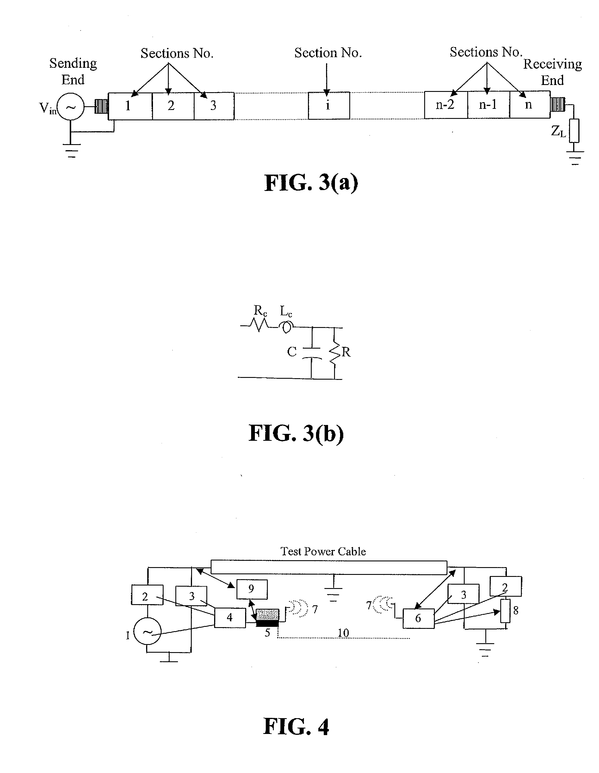
[0034]The disclosed cable diagnostic test methods, systems and apparatus utilize “standing wave” principles to identify and locate defect(s) along a power cable. As described herein, the disclosed methods / systems are effective in measuring dissipation factor (tan δ) and dielectric constant (∈′) associated with the insulation of a power cable, as well as the resistance (Rc) and inductance (Lc) associated with the conductor system, at discrete points along the cable's axial length. The disclosed methods / systems offer significant advantages for cable testing and related defect identification / location.

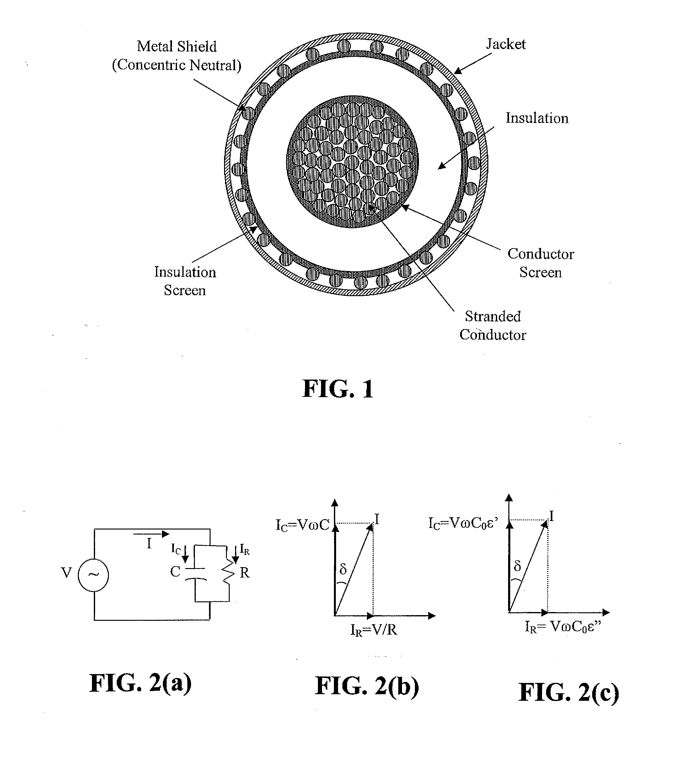
[0035]With reference to FIG. 2(a), the schematic circuit diagram represents a shielded power cable insulation subjected to an alternating voltage source, V=Vm sin(ωt), where Vm is the amplitude of the voltage and ω=2πf is the angular frequency, f being the frequency in Hz. The cable insulation is shown as a pure capacitance, C, across which is connected a resistance, R, representing the d...


PUM


Abstract

Cable diagnostic test methods, systems and apparatus are disclosed that utilize “standing wave” principles to facilitate identification and location of insulation defect(s) along a power cable. The methods/systems measure dissipation factors and dielectric constants associated with the power cable insulation and the impedance of the power cable conductor at any number of points or sections along the axial length of the cable. In an exemplary embodiment, the disclosed method involves (i) connecting an alternating voltage source to a cable at a “sending end” thereof; (ii) applying a voltage to the cable at a first frequency to set up a traveling wave along the cable that is reflected at the “receiving end” thereof; (iii) permitting a standing wave pattern to be established along the cable by the traveling wave and the reflection thereof; (iv) measuring the total complex power loss (Sin) at the sending end of the cable; (v) calculating the standing wave voltage at any point/section of the cable based on the load impedance (ZL) connected at the receiving end of the cable, and the characteristic impedance (ZO) of the cable, or the measured/calculated cable parameters for the first frequency of the voltage source, (vi) repeating the foregoing steps while one of: (1) varying at least one of: the load impedance (ZL) connected at the receiving end of the cable, the first frequency of the voltage source; the output impedance of the voltage source, a combination of the load impedance (ZL), the output impedance of the voltage source and the first frequency of the voltage source, and combinations thereof; (2) interchanging sending and receiving cable ends; and (3) a combination thereof, and (vii) determining a dissipation factor (tan δ) and a dielectric constant (∈′), for the insulation, and an impedance, for the conductor at predetermined points/sections along the axis of the cable.

Description

CROSS-REFERENCE TO RELATED APPLICATION[0001]The present application claims the benefit of a co-pending, commonly assigned provisional patent application entitled “Diagnostic Method for Electrical Cables Utilizing Axial Tomography Technique,” which was filed with the U.S. Patent and Trademark Office on Aug. 25, 2006 and assigned Ser. No. 60 / 840,229. The entire content of the foregoing provisional patent application is incorporated herein by reference.BACKGROUND[0002]1. Technical Field[0003]The present disclosure is directed to cable diagnostic test methods, systems and apparatus and, more particularly, to cable test methods, systems and apparatus that utilize “standing wave” principles to facilitate the identification and location of defect(s) along a power cable.[0004]2. Background Art[0005]With reference to FIG. 1, conventional shielded power cables generally consist of a conductor, normally fabricated from copper or aluminum, surrounded by a thin concentric semi-conducting screen,...

Claims


Application Information

Patent Timeline
IPC IPC(8): G01R31/11G01R31/08
CPCG01R31/1272G01R31/083
Inventor MASHIKIAN, MATTHEW S.
Owner INSTR MFG
Why Eureka
Try Eureka