Phase comparison signal processing circuit

a phase comparison and signal processing technology, applied in pulse generators, pulse manipulation, pulse techniques, etc., can solve the problems of not being able to freely set the reference frequency, and the high frequency setting of the reference frequency signal of the reference signal generator in the pll is actually subject to constraints, so as to improve the response speed and the synchronizable range. general

Inactive Publication Date: 2008-02-28
GEN RES OF ELECTRONICS INC
View PDF0 Cites 9 Cited by
  • Summary
  • Abstract
  • Description
  • Claims
  • Application Information

AI Technical Summary

Benefits of technology

[0018]As described above in detail, the phase comparison signal processing circuit brings about advantageous effects in that since the rectangular wave signal outputted from the phase comparator in the PLL is subjected to deformation processing to make it possible to increase the dc component in the rectangular wave signal and suppress the magnitude of a high frequency component contained in the dc component, the corner frequency of the loop filter can be transitioned in a high frequency direction as compared with the corner frequency of the conventional loop filter, so that the response speed of the PLL can be increased and the frequency width indicative of a synchronizable range of the PLL can be expanded.
[0019]In this case, to which extent the response speed of the PLL can be accelerated at the phase comparison signal processing circuit and to which extent the frequency width indicative of the synchronizable range can be expanded thereat differ depending upon various setting conditions such as the used format of digital phase comparator, the initial difference in phase between the oscillation signal of the voltage controlled oscillator and the reference signal, the loop gain of the PLL and the like. It is difficult to cite specific numeric values by way of example distinctly. However, both the response speed and the synchronizable range are generally improved a few times than before the use of the phase comparison signal processing circuit.

Problems solved by technology

However, the setting of the reference frequency signal of the reference signal generator in the PLL to the high frequency is actually subject to constraints due to the reasons to be described later where the PLL is used in the first local oscillation circuit in the multi-channel access receiver and the first local oscillation circuit in the frequency scanning receiver, for example.
Thus, it is not possible to freely set the reference frequency as mentioned above.
When, however, the corner frequency is set high, a ripple component contained in an output signal of the loop filter increases correspondingly, and a spurious component increases within the oscillation signal (carrier signal) outputted from the voltage controlled oscillator.

Method used


Image

  • Phase comparison signal processing circuit
  • Phase comparison signal processing circuit
  • Phase comparison signal processing circuit

Examples


first preferred embodiment

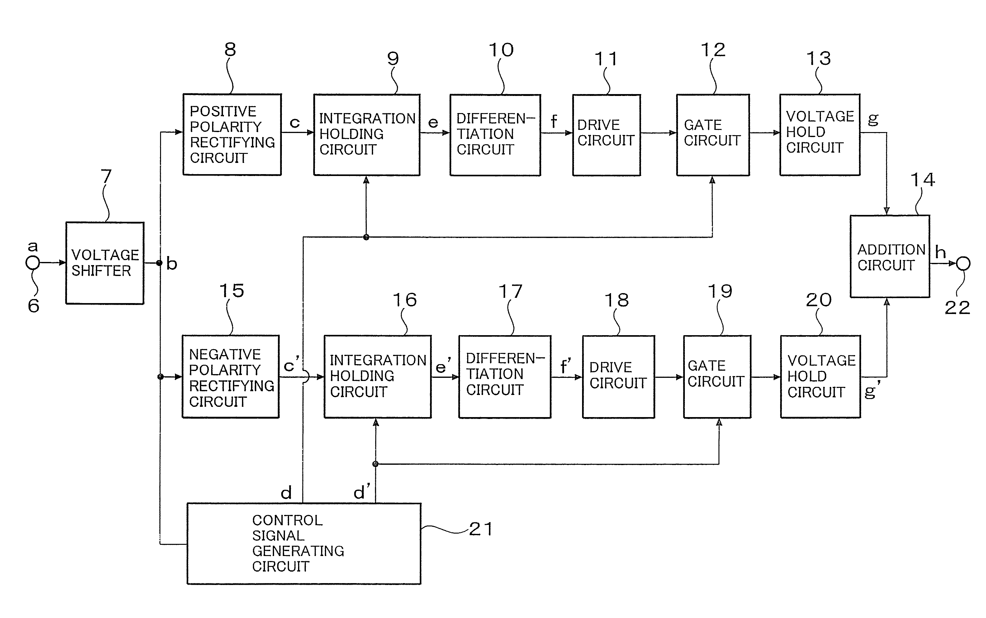
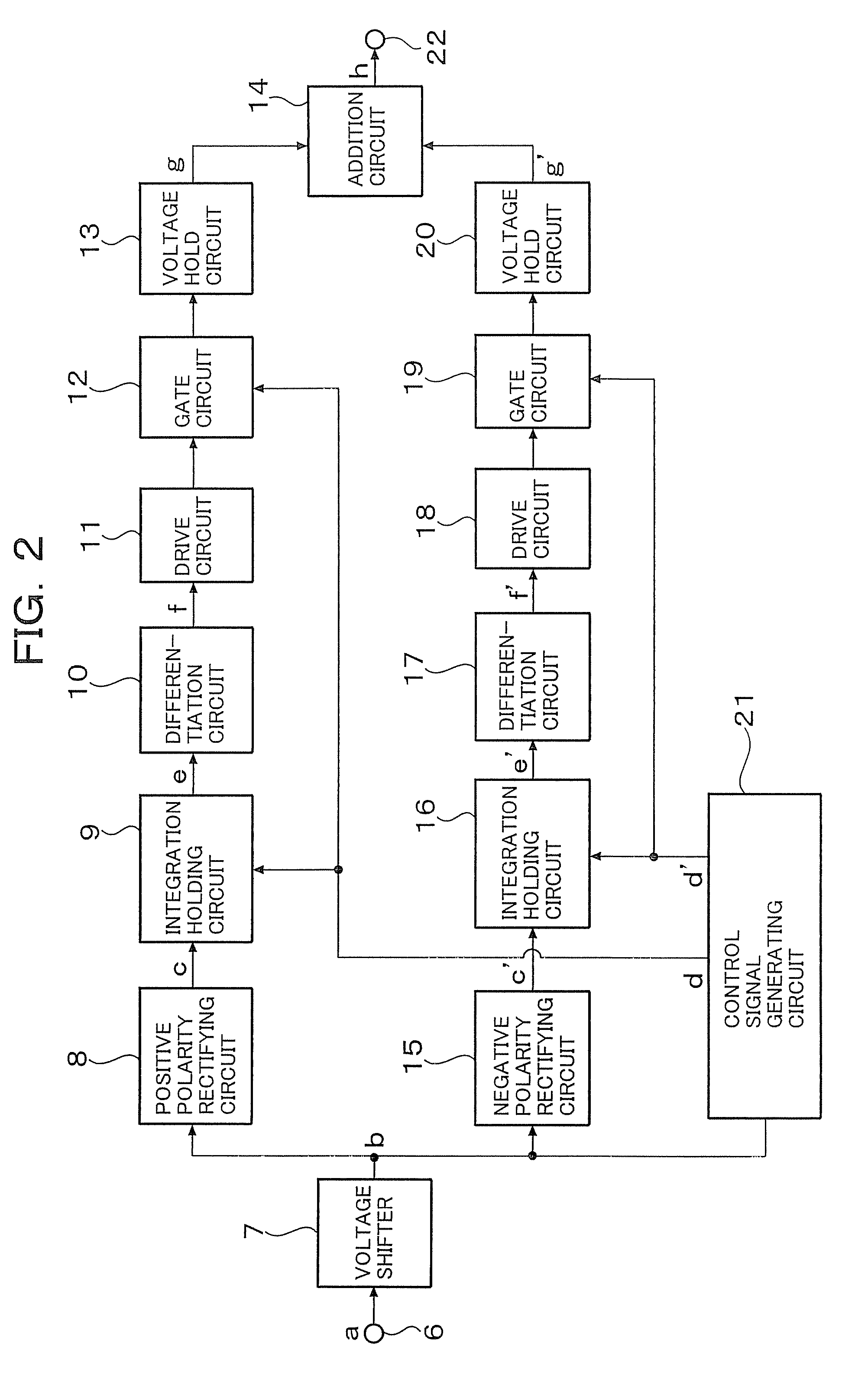
[0031]Next, FIG. 2 shows a first embodiment of a phase comparison signal processing circuit according to the present invention and is a block circuit diagram illustrating its fragmentary configuration.

[0032]As shown in FIG. 2, the phase comparison signal processing circuit according to the first embodiment comprises an input terminal 6, a voltage shifter 7, a positive polarity rectifying circuit 8, an integration holding circuit 9, a differentiation circuit 10, a drive circuit 11, a gate circuit 12, a voltage hold circuit 13, an addition circuit 14, a negative polarity rectifying circuit 15, an integration holding circuit 16, a differentiation circuit 17, a drive circuit 18, a gate circuit 19, a voltage hold circuit 20, a control signal generator or generating circuit 21, and an output terminal 22. In this case, the positive polarity rectifying circuit 8, the integration holding circuit 9, the differentiation circuit 10, the drive circuit 11, the gate circuit 12, the voltage hold ci...

second preferred embodiment

[0040]Next, FIG. 4 shows a second embodiment of a phase comparison signal processing circuit according to the present invention and is a block circuit diagram showing its fragmentary configuration. FIG. 4 illustrates an example in which all frequency spectrums contained in a processed signal changed in amplitude in a stepped wave fashion are diffused into the side of a frequency twice higher than the first embodiment.

[0041]As shown in FIG. 4, the phase comparison signal processing circuit according to the second embodiment is one wherein as compared with the phase comparison signal processing circuit according to the first embodiment, a drive circuit 23, a gate circuit 24, a voltage hold circuit 25 and an averaging circuit 26 are cascade-connected between an output terminal of an addition circuit 14 and an output terminal 2, and an addition circuit 27 for adding control pulses of a control signal generating circuit 21 and a delay circuit 28 for delaying the added control pulse of th...


PUM


Abstract

The present invention provides a phase comparison signal processing circuit which processes an output rectangular wave signal of a digital phase comparator of a PLL, expands a pullable-in frequency width of the PLL and shortens a synchronization time. The phase comparison signal processing circuit includes a first signal path which is parallel-connected between a voltage shifter for converting a rectangular wave signal to a bipolar signal and an output terminal and comprises a rectifying circuit, an integration holding circuit, a differentiation circuit, a gate circuit, a voltage hold circuit and a common addition circuit, a second signal path comprising a rectifying circuit, an integration holding circuit, a differentiation circuit, a gate circuit, a voltage hold circuit and the addition circuit, and a control signal generator for individually controlling the integration holding circuits and the gate circuits of the first and second signal paths. The rectification of the bipolar signal, integration and holding of rectified voltages, differentiation of integrated hold values, holding of differentiated outputs and addition of hold voltages are carried out at the first and second signal paths thereby to output a processed signal.

Description

RELATED / PRIORITY APPLICATION[0001]This application claims priority with respect to Japanese Application No. 2006-200742 filed Jul. 24, 2006.BACKGROUND OF THE INVENTION[0002]1. Field of the Invention[0003]The present invention relates to a phase comparison signal processing circuit, and particularly to a phase comparison signal processing circuit which is connected between a phase comparator and a loop filter employed in a phase-locked loop (PLL) and processes a rectangular wave signal for frequency comparison outputted from the phase comparator and supplied to the loop filter and which enlarges a pull-in frequency width at the PLL and improves a synchronous characteristic such as shortening of a synchronization time.[0004]2. Description of the Related Art[0005]A PLL has been used in a large number of electronic equipment each requiring an oscillator in recent years because the oscillation frequency of a voltage controlled oscillator can automatically be controlled to a predetermined...

Claims


Application Information

Patent Timeline
Patent Type & Authority Applications(United States)
IPC IPC(8): H03L7/06H03K3/86
CPCH03L7/1077H03L7/093
Inventor KAWAI, KAZUO
Owner GEN RES OF ELECTRONICS INC
Why Eureka
Try Eureka