System and method for printing data carrying mark on honeycomb structures

Inactive Publication Date: 2008-03-06
DEETER LEE EDGAR +6
View PDF22 Cites 20 Cited by
  • Summary
  • Abstract
  • Description
  • Claims
  • Application Information

AI Technical Summary

Benefits of technology

[0011]Preferably, the printed mark is in the form of a bar code, such as a two-dimensional data matrix barcode that includes unique manufacturing information relating to the specific ceramic structure that it is printed on. Such manufacturing information may be selected from the group consisting of: the identification of the specific factory of origin, identification of the specific kiln used, identification of the specific batch number, identification of the specific date of green body manufacture, and a unique individual identification number. Such a unique barcode is preferably printed on each ceramic honeycomb structure. The use of a two dimensional matrix bar code provides a robust record of the information contained within the mark. In particular, as much as 30% of the mark can be obliterated without loss of information. In addition to the machine-readable bar code, such as the two-dimensional data matrix, the mark preferably also includes a human-readable data string, such as an alphanumeric, to facilitate ex

Problems solved by technology

Unfortunately, due to the thinness of the outer skin and the inner cell-forming webs, the substantial thermal stresses that the unfinished ceramic structures undergo during the firing processes, and the necessary mechanical handling of the green and fired bodies during the manufacturing process, defects such as internal cracks and voids may occur, as well as separations between the outer skin and the inner matrix of webs.
Additionally, upsets due to raw material deviations from specifications may also occur possibly leading to property variations.
Unfortunately, the applicants have observed that such a marking procedure does not reliably result in an accurate recovery of the manufacturing information associated with a particula

Method used


Image

  • System and method for printing data carrying mark on honeycomb structures
  • System and method for printing data carrying mark on honeycomb structures
  • System and method for printing data carrying mark on honeycomb structures

Examples


Example

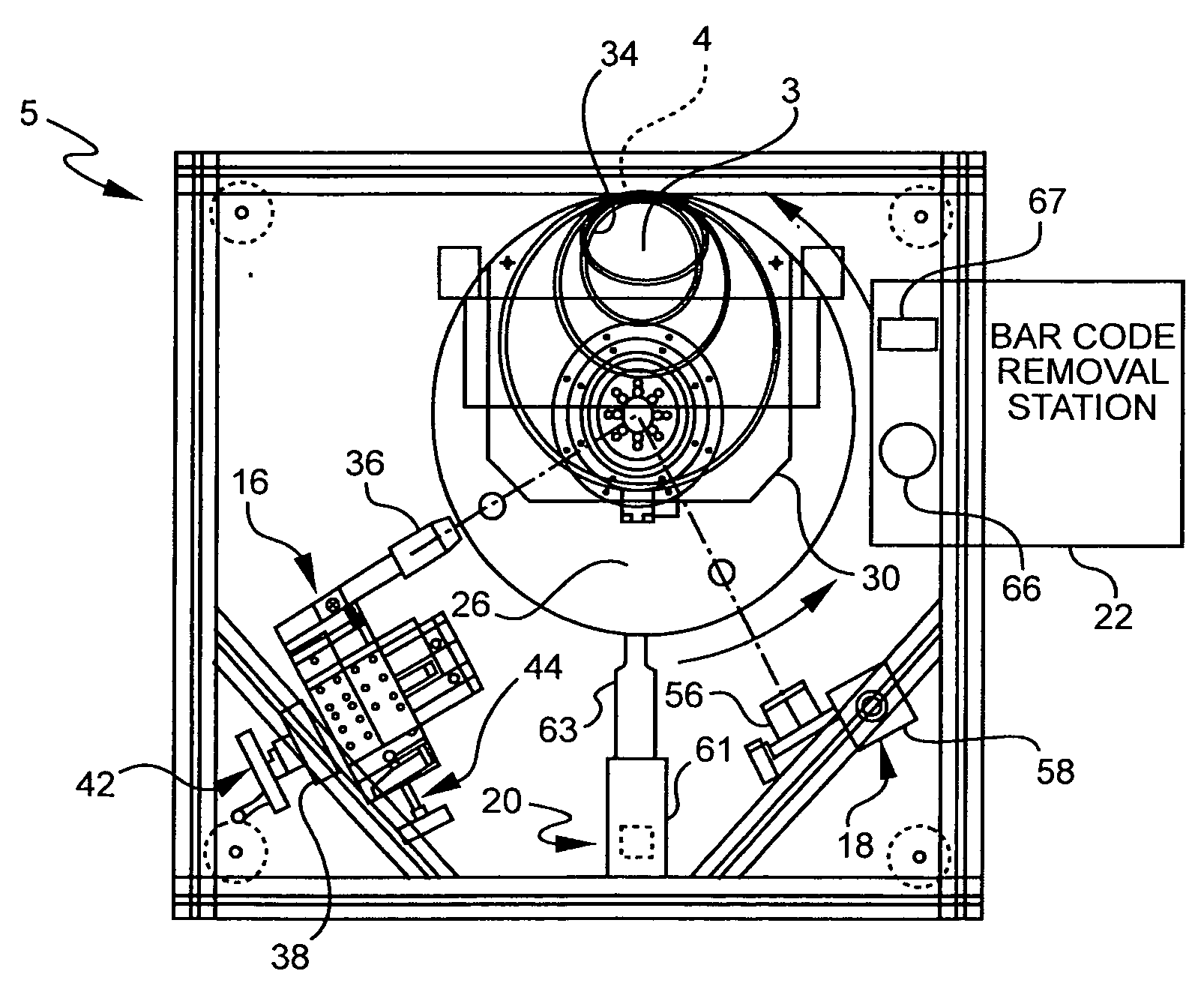
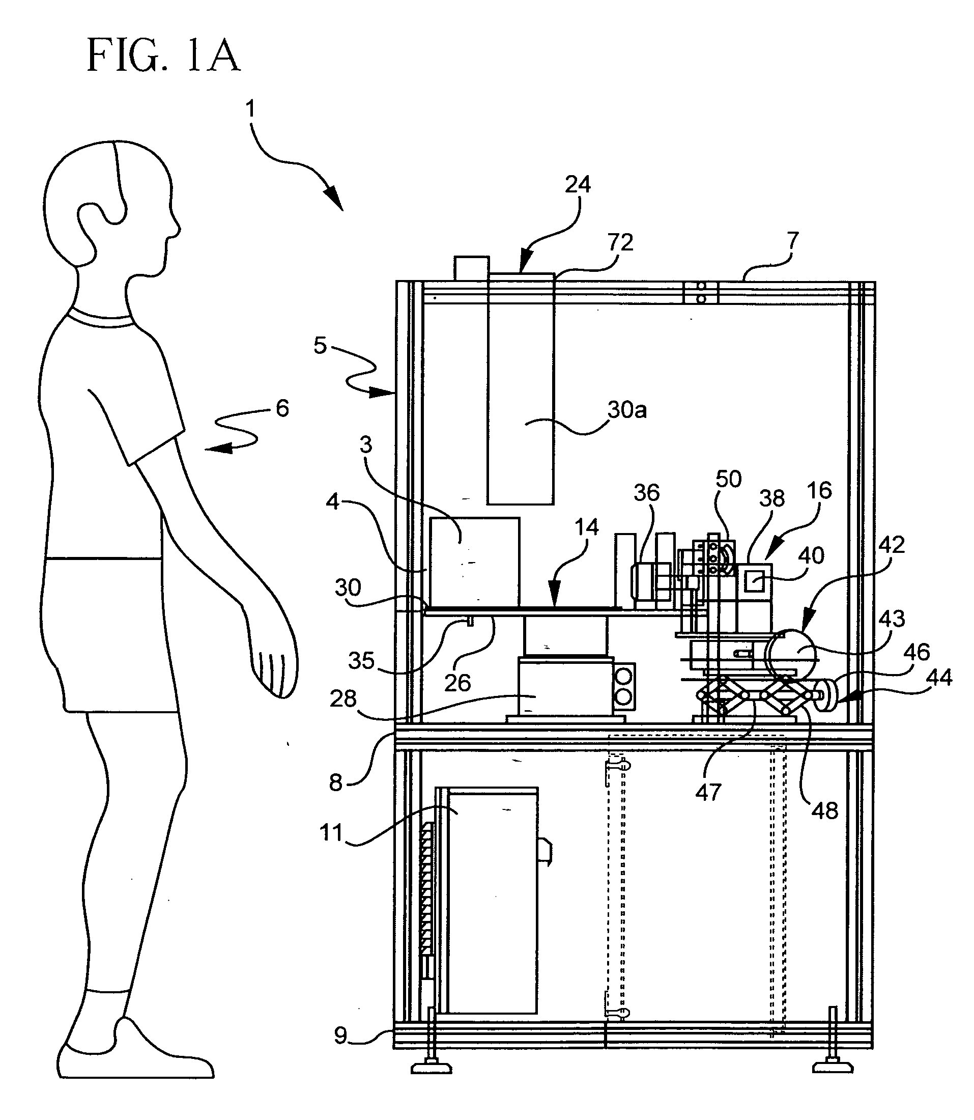
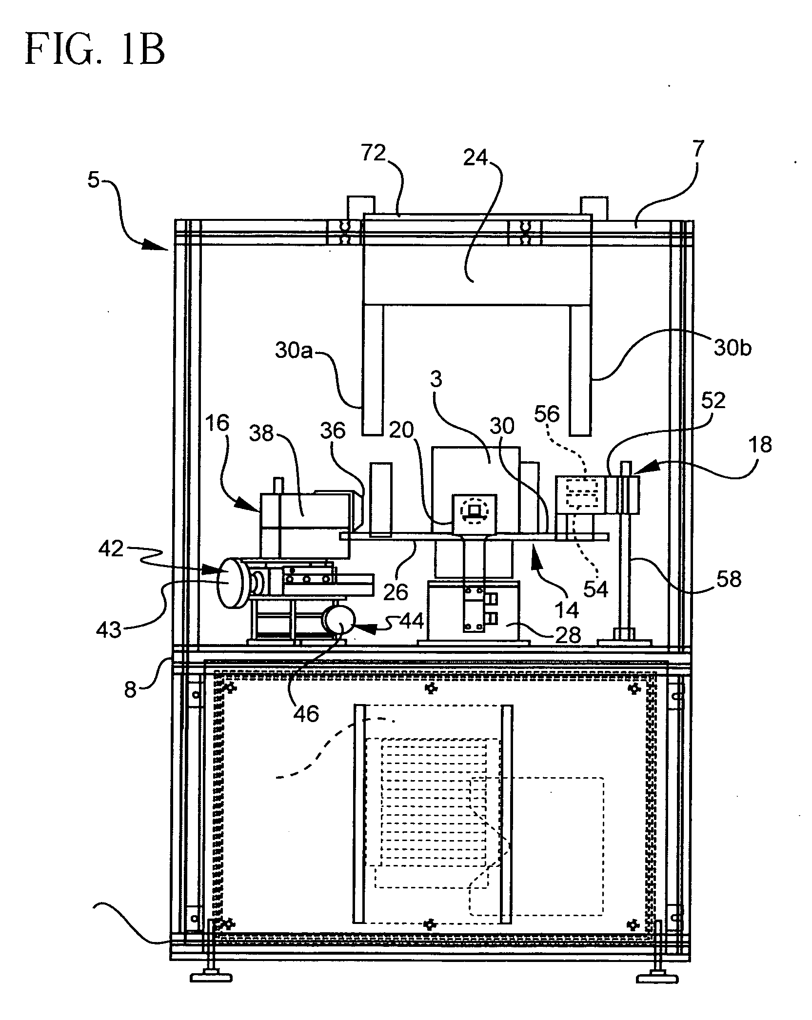
[0030]With reference now to FIGS. 1A and 1B, wherein like numerals designate like components throughout all the several figures, the system 1 for marking green body or otherwise unfinished ceramic structure 3 of a ceramic honeycomb structure generally comprises a marking station 5, and a station worker 6 for loading and unloading the green body 3. The marking station 5 includes an upper frame 7, an upper shelf 8, and a lower shelf 9. The lower shelf 9 supports a programmable logic controller 11 which controls the operation of the various components mounted on the upper shelf 8. The upper shelf 8 supports a moving assembly 14, a printer 16 for printing a data-carrying mark on the green body 3, an optical reader 18 for reading and determining the overall equality of the printed mark, a dryer 20 for drying the ink that forms the mark, and a bar code removing assembly 22 (shown in FIGS. 2-5) for removing and covering defectively-printed marks from the green body 3. Each of these princip...


PUM

PropertyMeasurementUnit
Temperatureaaaaaaaaaa
Fractionaaaaaaaaaa

Abstract

A system, method, and ink for printing a data carrying mark on a green ceramic honeycomb structure is provided. The system includes a printer having an ink jet print head that prints a mark, preferably in the form of a two-dimensional data matrix barcode, on a side wall of the green ceramic honeycomb structure. The ink may be a heat resistant ink that comprises a mixture of a glass or glass ceramic frit and a metal oxide colorant. An optical reader is provided for determining if the data is accurately reproduced in the printed mark, as well as any noise factor which may be present due to defective printing. The system includes a turntable that positions the green body for the printing operation, and then rotates the green body to position the printed mark first in front of a dryer, and then in front of the optical reader to determine the quality of the mark. Marked green and ceramic honeycombs are also provided as well as a method for repairing a defective applied bar code on a honeycomb structure.

Description

RELATED INVENTIONS[0001]This invention claims priority to, and the benefit of, U.S. Provisional Application No. 60 / 841,074 filed Aug. 30, 2006 and entitled “System And Method For Printing A Data Carrying Mark On A Ceramic Structure” and U.S. Provisional Application No. 60 / 861,914 filed Nov. 30, 2006 and entitled “Method of Printing a Data Carrying Mark on an Unfinished Ceramic Structure, and Structures Made Thereby.”FIELD OF THE INVENTION[0002]This invention generally relates to marking of ceramic structures, and is specifically concerned with systems and methods for printing a data-carrying mark on a honeycomb structure, and marked honeycomb structures produced thereby.BACKGROUND OF THE INVENTION[0003]Ceramic honeycomb structures are widely used as anti-pollutant devices in the exhaust systems of automotive vehicles, both as catalytic converter substrates in automobiles, and diesel particulate filters in diesel-powered vehicles. In both applications, the ceramic honeycomb structure...

Claims


Application Information

Patent Timeline
IPC IPC(8): B41J29/38B41J2/01
CPCB41J3/4073B41M5/007C04B41/009C04B41/4572C04B41/81C04B2111/00793C04B2111/0081F01N3/0222F01N2260/24C03C8/14B41M5/0047C04B41/4539C04B41/4578C04B41/5022C04B2103/54C04B35/00C04B35/195C04B38/0006B28B23/0031
Inventor DEETER, LEE EDGARJOHNSON, L. URDENISLAMBERSON, LISA ANNMCINTOSH, JOSEPH JAMESMEROLA, DIANA MARIEMORENA, ROBERT MICHAELRUMSEY, DENNIS FAY
Owner DEETER LEE EDGAR
Why Eureka
Try Eureka