Receiving Circuit and Optical Signal Receiving Circuit
- Summary
- Abstract
- Description
- Claims
- Application Information
AI Technical Summary
Benefits of technology
Problems solved by technology
Method used
Image
Examples
first embodiment
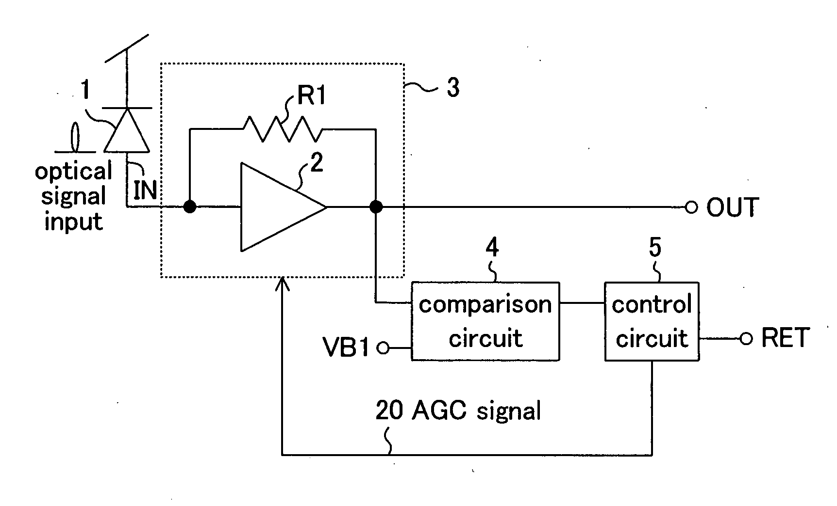
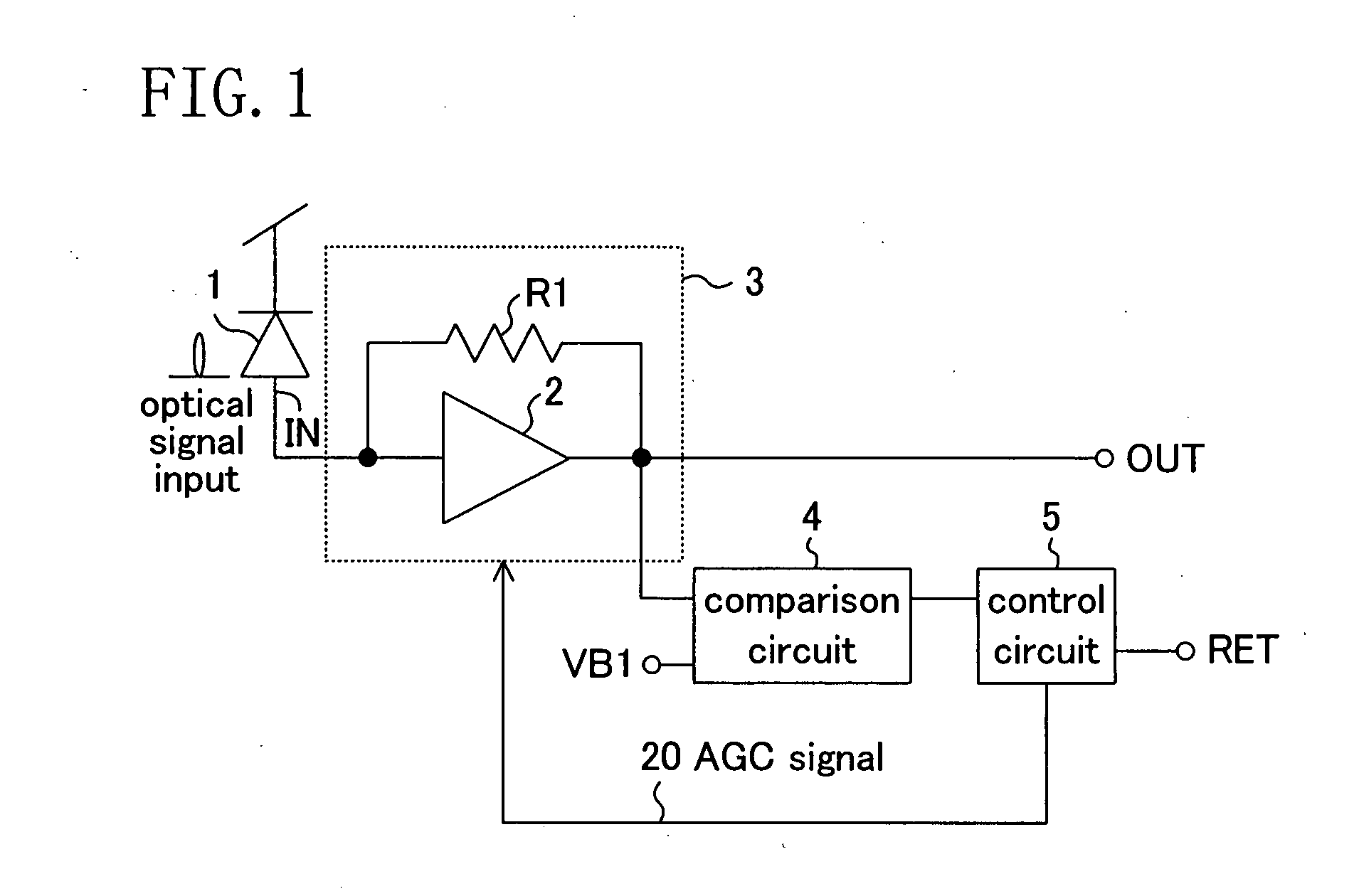
[0100] Initially, a first embodiment of a light receiving circuit of the present invention will be described with reference to FIG. 1.
[0101] The light receiving circuit of FIG. 1 comprises: a light receiving element 1 for receiving an optical input signal and outputting a current proportional to the intensity of the input light; a transimpedance amplifier 3 comprising an inversion amplifier 2 for amplifying an electrical signal which is an output current obtained by photoelectric conversion of the light receiving element 1 and a feedback resistance R1 connected between an input IN and an output OUT of the inversion amplifier 2; a comparison circuit 4 for receiving an output of the transimpedance amplifier 3, comparing the output with a reference value (first comparative value) VB1 which is set to have a certain desired value to determine the level of the output of the transimpedance amplifier 3, and outputting the comparison result; and a control circuit 5 for holding the compariso...
second embodiment
[0182] Next, a second embodiment of the receiving circuit of the present invention will be described with reference to FIG. 8.
[0183] The receiving circuit of this embodiment in which a register circuit is used to successively hold the comparison result of the comparison circuit 4, is different from that of the first embodiment in which the control circuit 5 of the receiving circuit uses the latch circuit to hold the comparison result of the comparison circuit 4.
[0184] Here, parts other than the register circuit have been described in the first embodiment, and therefore, the same parts will not be described.
[0185] A control circuit 5 included in the receiving circuit of this embodiment of FIG. 8 comprises: shift register circuits 11a, 11b, . . . for successively holding a comparison result output from a comparison circuit 4; and a control signal generating circuit 7 for generating an AGC signal 20 which is a control signal for adjusting the gain of a transimpedance amplifier 3 bas...
third embodiment
[0193] Next, a third embodiment of the receiving circuit of the present invention will be described with reference to FIG. 9.
[0194] The receiving circuit of this embodiment of FIG. 9 is different from that of the first embodiment in that a reference value generating circuit 12 for generating an intermediate value of the output of the transimpedance amplifier 3, and a differential amplification circuit 13 for receiving the output of the transimpedance amplifier and the output of the reference value generating circuit 12 to generate a differential signal, are further provided.
[0195] When a differential signal is required in a subsequent amplifier circuit (e.g., in data communication, etc.), since the output signal OUT is a single signal in the configuration of the first embodiment of the present invention, single-differential conversion as described in the present invention is required.
[0196] Also, the reference value generating circuit 12 can be initialized by inputting a reset si...
PUM
 Abstract
Description
Claims
Application Information
 - R&D
- Intellectual Property
- Life Sciences
- Materials
- Tech Scout
- Unparalleled Data Quality
- Higher Quality Content
- 60% Fewer Hallucinations
Browse by: Latest US Patents, China's latest patents, Technical Efficacy Thesaurus, Application Domain, Technology Topic, Popular Technical Reports.
© 2025 PatSnap. All rights reserved.Legal|Privacy policy|Modern Slavery Act Transparency Statement|Sitemap|About US| Contact US: help@patsnap.com


