
Clock generation for synchronous circuits with slow settling control signals

a control signal and synchronous circuit technology, applied in the field of synchronous circuits, can solve the problems of high clock rate used in these circuits, signal on some signal lines driving multiple modules may not settle to be reliably sampled, and design constraints in high-speed interface circuits

Active Publication Date: 2008-03-06
ATI TECH INC
View PDF5 Cites 19 Cited by
  • Summary
  • Abstract
  • Description
  • Claims
  • Application Information

AI Technical Summary

Benefits of technology

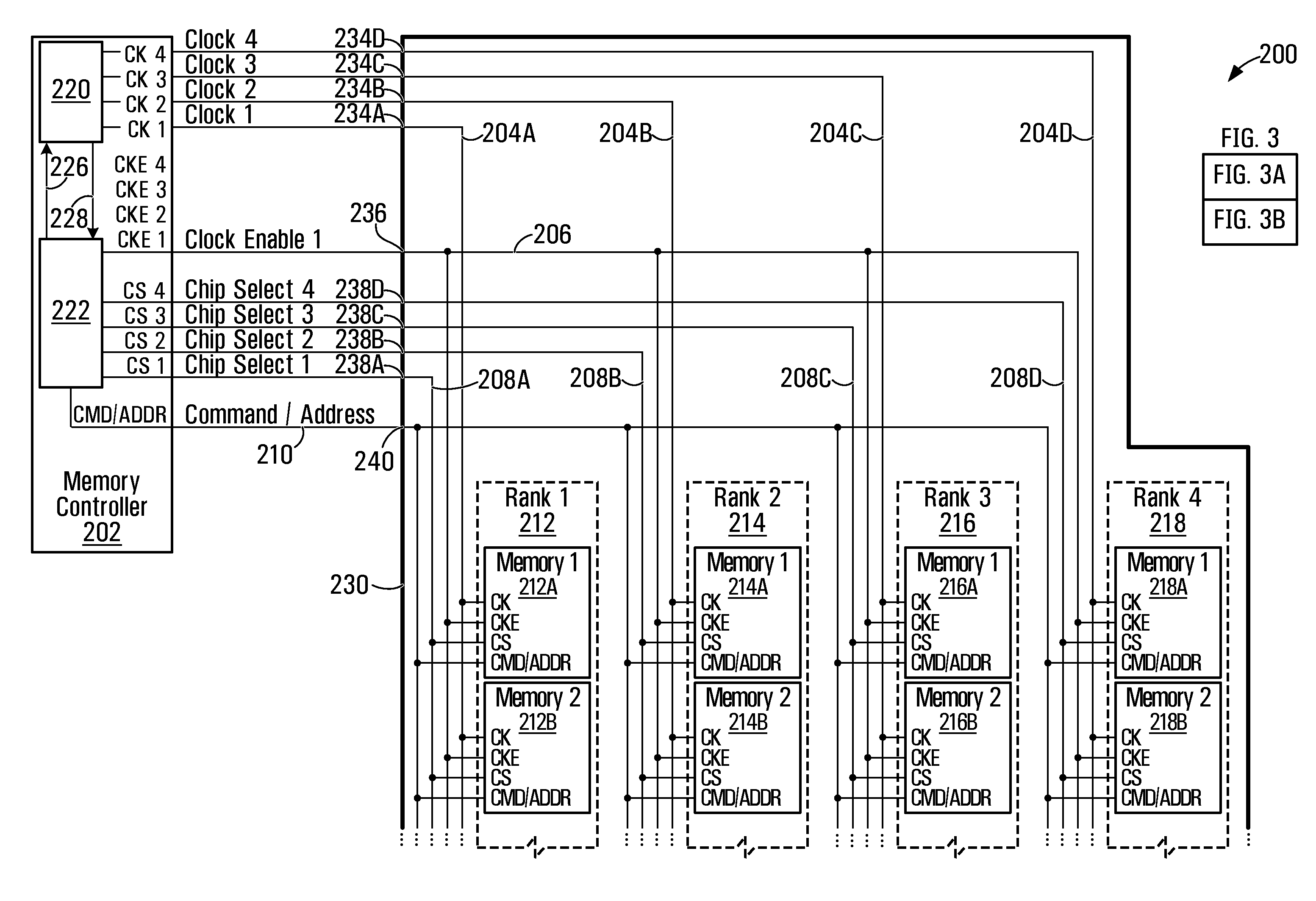
[0010]In accordance with one aspect of the present invention, there is provided, a method of operating a synchronous digital circuit including a clock input and at least one control signal input. The digital circuit has a normal state and a lower power consumption state. The method involves providing a clock signal through the clock input providing a control signal through the control signal input to place the synchronous digital circuit in a lower power consumption state. The control signal takes longer than one cycle of the clock signal to settle. The method involves concurrently suppressing the clock signal at the clock input for at least the duration time that the control signal needs to settle. This prevents sampling of the control signal before it has settled.
[0012]In accordance with another aspect of the present invention, there is provided, a memory circuit, including a plurality of ranks of synchronous memory, each of the ranks having a first control signal input and a clock input; a controller including a control signal generator providing a shared signal to the first control signal inputs of the of ranks, and a clock generator providing a clock to the clock inputs of the ranks. The control signal generator is in communication with the clock generator to suppress the clock for a defined duration as a control signal is provided by the control signal generator. The defined duration allows the control signal to settle to allow each of the ranks of synchronous memory to unambiguously sample the control signal.
[0015]In accordance with another aspect of the present invention, there is provided, a memory controller including a control signal generator that provides a shared signal to a plurality of ranks of synchronous memory. Each of the ranks has a first control signal input and a clock input. The clock generator provides a clock to the clock inputs of the ranks. The control signal generator communicates with the clock generator to suppress the clock for a defined duration as a control signal is provided by the control signal generator. The defined duration allows the control signal to settle, which allow each ranks to unambiguously sample the control signal.

Problems solved by technology

As clock rates used in these circuits are very high, signals on some signal lines drive multiple modules may not settle to be reliably sampled within one clock cycle.
Such design constraints in high speed interface circuits, in which signal lines interconnect many modules, are often difficult to meet.
Stringent timing constraints are particularly difficult to meet on a signal line that is interconnected to multiple modules, as the trace characteristic impedance connecting the multiple modules, and the capacitive load of the multiple modules may not permit fast settling of the signal to a desired signal level.
If timing requirements are not met, signals may be ambiguously or inaccurately decoded.
Unfortunately, providing multiple drivers and routing multiple individual lines connected to individual modules, rather than sharing the same signal line is often complex and expensive.
All these factors increase the cost of manufacturing the circuit.

Method used


Image

  • Clock generation for synchronous circuits with slow settling control signals
  • Clock generation for synchronous circuits with slow settling control signals
  • Clock generation for synchronous circuits with slow settling control signals

Examples


Embodiment Construction

[0026]A typical example of high speed synchronous multi-module circuit is a synchronous dynamic random access memory (SDRAM) circuit. SDRAM is used in many computing devices such as portable (laptop) computers, desktops and workstations. SDRAM typically allows for data transfer at speeds in excess of conventional DRAM or static random access memory.

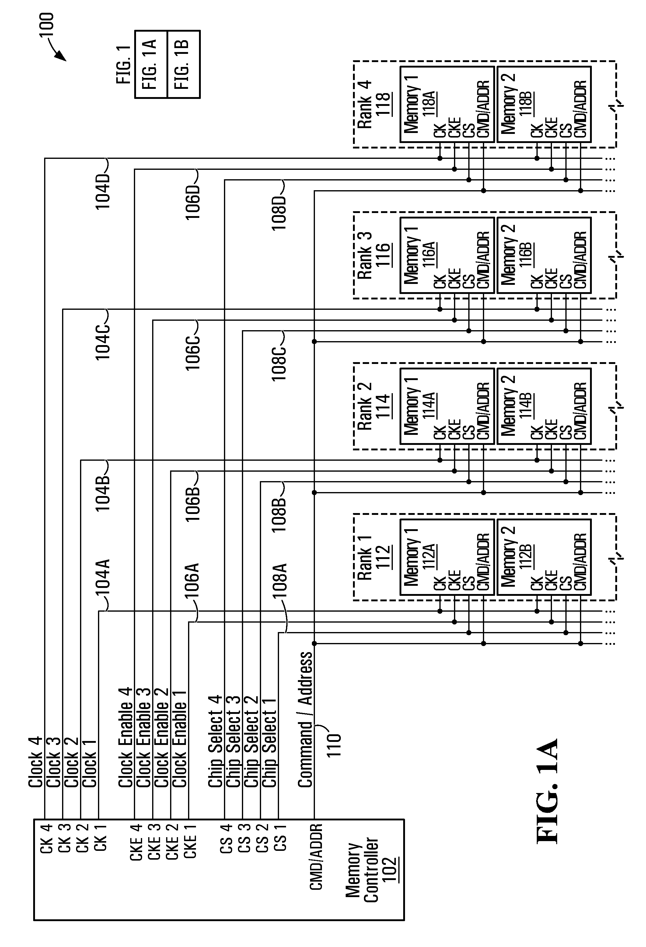
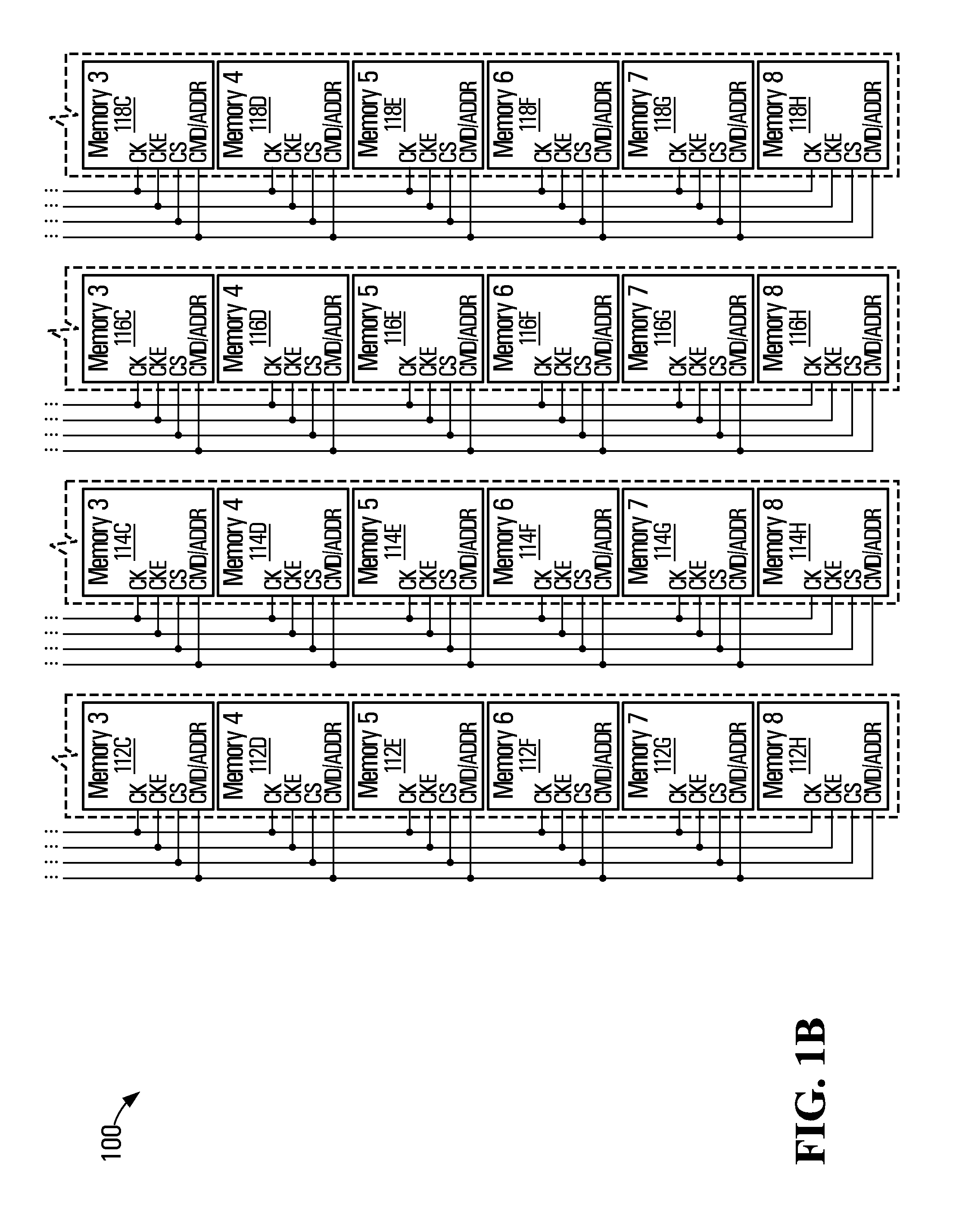
[0027]A schematic diagram of a conventional SDRAM circuit 100 is illustrated in FIG. 1. Circuit 100 includes a memory controller 102, and memory ranks 112, 114, 116, and 118. Each memory rank in turn includes a number of memory cells. For example, memory rank 112 includes cells 112A, 112B, 112C, 112D, 112E, 112F, 112G, 112H. Memory rank 114 includes cells 114A, 114B, 114C, 114D, 114E, 114F, 114G, 114H. Memory rank 116 includes cells 116A, 116B, 116C, 116D, 116E, 116F, 116G, 116H. Memory rank 118 includes cells 118A, 118B, 118C, 118D, 118E, 118F, 118G, 118H.

[0028]Command / address lines 110 interconnect memory controller 102 to memory ranks ...


PUM


Abstract

A circuit includes a clock generator for providing a clock signal to a synchronously operated digital circuit and a control signal generator for providing a control signal to the synchronously operated digital circuit. The control signal generator is interconnected to the clock generator to suppress the clock signal for a defined duration as a control signal is provided. The defined duration allows the control signal to settle to allow said synchronously operated digital circuit to unambiguously sample said control signal. The control signal generator may place the synchronous digital circuit in a lower power consumption state.

Description

FIELD OF THE INVENTION[0001]The present invention relates generally to synchronous circuits, and more particularly to synchronous circuits in which control signals do not settle within one clock cycle, and methods and controllers for unambiguously sampling such control signals.BACKGROUND OF THE INVENTION[0002]High speed synchronous circuits in which a controller drives multiple loads are known. Typical examples include synchronous dynamic random access memory (SDRAM) circuits with multiple memory ranks. In synchronous circuits, a controller typically provides a common clock used to provide a common timing reference.[0003]As clock rates used in these circuits are very high, signals on some signal lines drive multiple modules may not settle to be reliably sampled within one clock cycle. Thus, designs that take this into account usually allow slow settling signals connected to multiple modules to settle in two or three clock cycles. Such timing arrangements, in which signals are not sa...

Claims


Application Information

Patent Timeline
IPC IPC(8): G06F1/04
CPCG06F1/06G06F1/3225G11C7/22G11C5/04G11C5/00
Inventor BOSKOVIC, BORIS
Owner ATI TECH INC
Learn More