Method, System, and Program Product for Automated Verification of Gating Logic Using Formal Verification

Inactive Publication Date: 2008-03-06
GLOBALFOUNDRIES INC
View PDF21 Cites 11 Cited by
  • Summary
  • Abstract
  • Description
  • Claims
  • Application Information

AI Technical Summary

Problems solved by technology

Since a single fence line typically serves to protect a multitude of interface signals from causing downstream logic activity to occur, simulation alone is typically not sufficient to provide coverage on every

Method used


Image

  • Method, System, and Program Product for Automated Verification of Gating Logic Using Formal Verification
  • Method, System, and Program Product for Automated Verification of Gating Logic Using Formal Verification
  • Method, System, and Program Product for Automated Verification of Gating Logic Using Formal Verification

Examples


Embodiment Construction

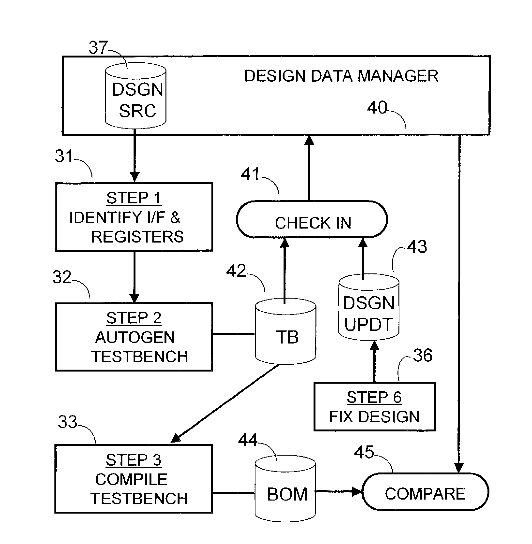
[0017]As described herein the automated verification methodology parsing scripts auto generate test bench, e.g., VHDL or Verilog or the like, from the design source, such as VHDL or Verilog or the like. A formal verification model is then built with the model comprising the testbench VHDL or Verilog and the design under test. The resulting design verification tool then provides proofs and counterexamples for all of the rules, e.g., auto-generated rules, in the test bench.

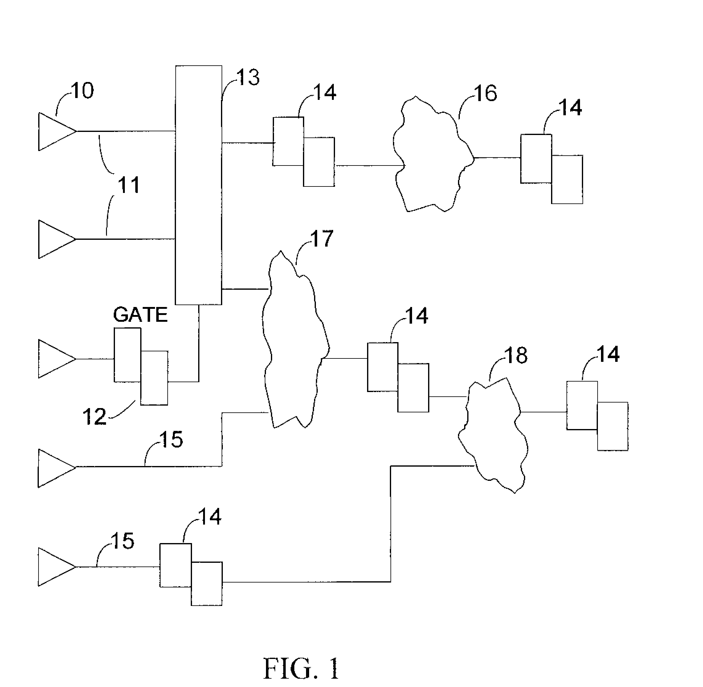
[0018]Turning to FIG. 1, the Figure depicts a typical arrangement of latch devices (14) and combinatorial logic. Although the preferred embodiment illustrates master-slave latches, one skilled in the art will appreciate that the present invention will work with any type of latch that can be modeled in a verification environment. Receiver circuits (10) may represent chip I / O, or internal macro I / O. In this figure they show various interface signals being received into the design under test. Interface signals (11) dep...


PUM


Abstract

As described herein the automated verification methodology parsing scripts auto generate test bench hardware design langaue, such as VHDL or Verilog, from the design source VHDL or Verilog. A formal verification model is then built comprising the testbench VHDL and the design under test. The resulting design verification tool then provides proofs and counterexamples for all of the rules, e.g., auto-generated rules, in the test bench.

Description

BACKGROUND[0001]1. Field of the Invention[0002]The invention relates to methods, systems, and program products for evaluating the behavior of designed circuit components, by, for example, transforming a high-level, multi-domain design into its hardware implementation.[0003]2. Background Art[0004]Gating logic is an essential part of systems with multiple chips or multiple clock domains. The purpose of gating logic is to prevent spurious logic activity from “contaminating” a domain under test while the system is in the process of being reset or reconfigured. That is, when an incoming fence signal is active on a particular chip or domain, the internal logic on the chip or domain must be impervious to random transitions that may be present on any number of incoming interface busses or signals.[0005]Thus, a complete verification of gating logic requires demonstration that all logic associated with a particular fence or set of fences is effectively quiesced during any window of time that ...

Claims


Application Information

Patent Timeline
IPC IPC(8): G06F17/50
CPCG06F17/504G06F30/3323
Inventor SEIGLER, ADRIAN E.VAN HUBEN, GARY A.
Owner GLOBALFOUNDRIES INC
Why Eureka
Try Eureka