Micro-actuator and locking switch

a technology of locking switch and micro-actuator, which is applied in the direction of micro-structural devices, contacts, relays, etc., can solve the problems of high temperature processes that will destroy such wires, their response time is extremely short, and their power consumption is minimal, and achieves the effect of reducing creep and low impedan

Active Publication Date: 2008-03-13
WSOU INVESTMENTS LLC
View PDF7 Cites 3 Cited by
  • Summary
  • Abstract
  • Description
  • Claims
  • Application Information

AI Technical Summary

Benefits of technology

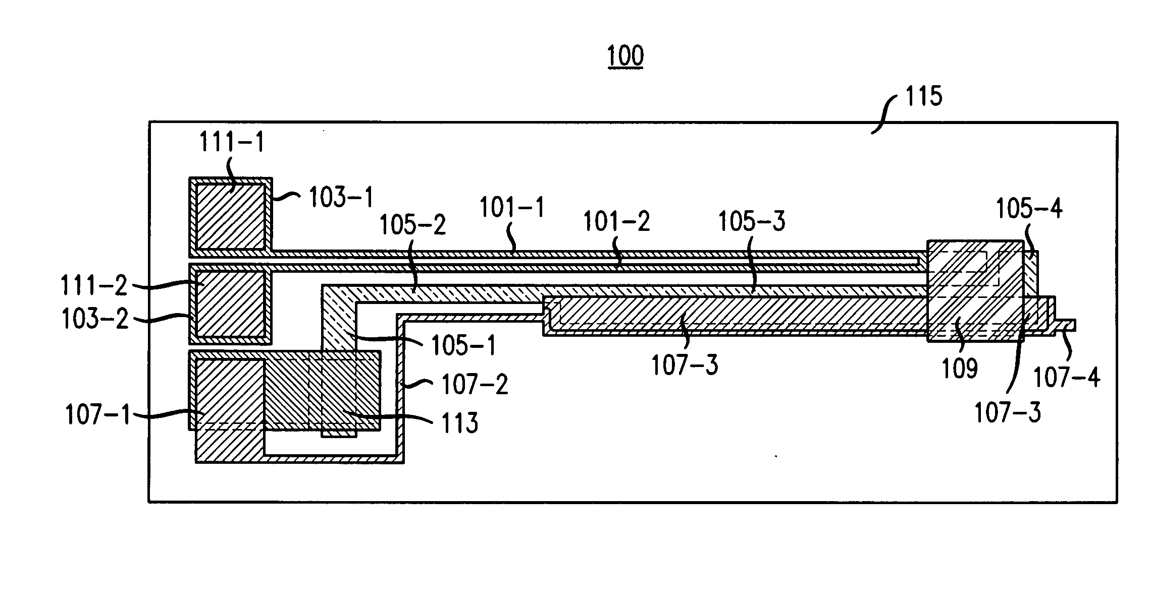
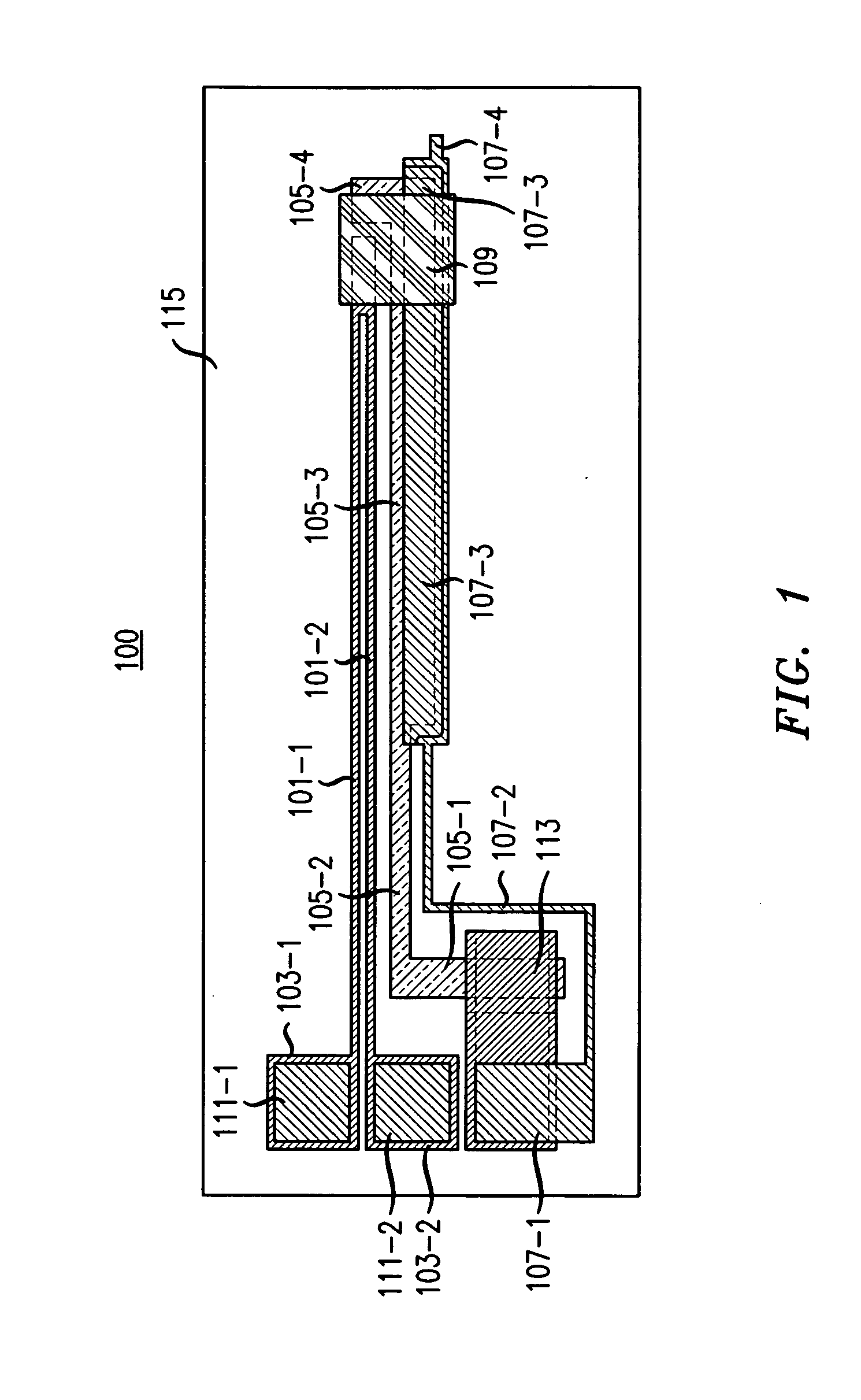
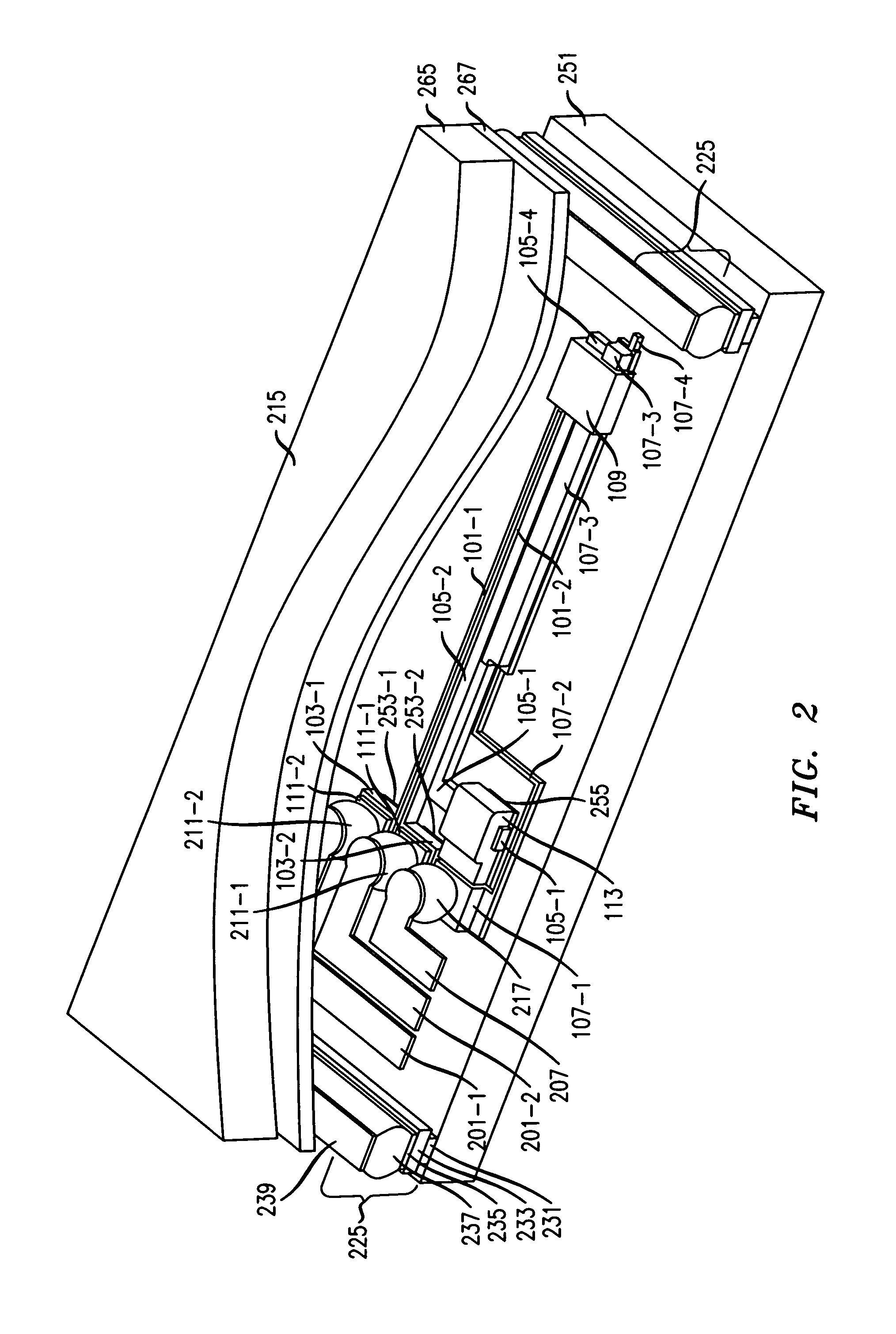
[0016]Advantageously, when appropriately designed, e.g., such that the hot arm provides sufficient force to bend the cold arm when the hot arm is heated, yet is soft enough to not impede restoration of the cold arm to its initial position when the hot arm cools, such an actuator does not suffer from creep, due to the restorative force provided by the silicon is essentially unchanging over time. Further advantageously, the high temperature processing of the silicon, which is only need to form the cold arm, is isolated from the processing of the metal used in the switch because 1) the conductors for routing the electrical control currents to the various hot arms for heating them as well as the signals to be switched by the various switches are on the second chip which is independently fabricated, and 2) any wires on the first chip, such as the wires making up each hot arm and each wire coupled to the cold arm and carrying the signal to be switched, can be manufactured on the first chip after the silicon processing is complete. Further advantageously, use of a wire associated with the cold arm, but not the cold arm itself, to carry the signal to be switched, allows the cold arm to be made of silicon, thereby eliminating creep, while yet allowing the signal wire to have low impedance.

Problems solved by technology

Typically, their power consumption is minimal and their response time is extremely short, e.g., the complete sequence for closing or opening a MEMS switch may be only a few milliseconds.
Furthermore, the contact does not electrically connect the pair of switch contacts when the second tab engages the first tab between the pair of switch contacts and the first tab.
Unfortunately, high temperature processes will destroy such wires.
However, disadvantageously, metal suffers from so-called “creep”, meaning failure of the restorative force properties of the metal to return it to its original shape when the force upon the metal that distorted its shape is removed.
By contrast, silicon does not suffer from creep, but it has relatively high resistance, making it unsuitable to be used as the electrical conductor for signals to be switched by such a switch.
Furthermore, silicon requires high temperatures for processing to form elements therefrom, such high temperature processing being inimicable to the underlying wires.
Lastly, the thermal expansion of silicon is relatively limited as compared to that of metal, in that silicon does not deflect as strongly as a typically employed metal would upon heating, and hence silicon is relatively unsuitable for use as the hot arm.

Method used


Image

  • Micro-actuator and locking switch
  • Micro-actuator and locking switch
  • Micro-actuator and locking switch

Examples


Embodiment Construction

[0024]The following merely illustrates the principles of the invention. It will thus be appreciated that those skilled in the art will be able to devise various arrangements that, although not explicitly described or shown herein, embody the principles of the invention and are included within its spirit and scope. Furthermore, all examples and conditional language recited herein are principally intended expressly to be only for pedagogical purposes to aid the reader in understanding the principles of the invention and the concepts contributed by the inventor(s) to furthering the art, and are to be construed as being without limitation to such specifically recited examples and conditions. Moreover, all statements herein reciting principles, aspects, and embodiments of the invention, as well as specific examples thereof, are intended to encompass both structural and functional equivalents thereof. Additionally, it is intended that such equivalents include both currently known equivale...


PUM


Abstract

A micro-electromechanical actuator employs metal for the hot arm and silicon for at least the flexible portion of the cold arm. The cold arm made of silicon is coupled to a metal wire that moves with it and is used to carry the signal to be switched when at least two of such actuators are formed into a switch. Arrays of such switches on a first chip may be cooperatively arranged with a second chip that is flip-chip bonded to the first chip, the second chip having thereon wires routing the electrical control currents to the various hot arms for heating them as well as the signals to be switched by the various switches.

Description

TECHNICAL FIELD[0001]This invention relates to micro-actuators that are especially useful for micro-switches such as relays, and more particularly, to arrays of locking micro-switches using such micro-actuators.BACKGROUND OF THE INVENTION[0002]Micro-electromechanical systems (MEMS) are very small movable mechanical structures built using standard semiconductor processes. MEMS can be arranged to function as actuators, which are useful in many applications. These actuators typically have a length of a few hundreds of microns, and oftentimes a width of only a few tens of microns. A MEMS actuator is usually configured and disposed in a cantilever fashion in that it has an end attached to a substrate and an opposite free end which is movable between at least two positions, one being a neutral position and the others being deflected positions.[0003]One possible use for MEMS actuators is to configure them as switches. These switches may be locking switches, i.e., relays. These switches are...

Claims


Application Information

Patent Timeline
Patent Type & Authority Applications(United States)
IPC IPC(8): H01L29/82
CPCB81B3/0024B81B2201/018H01H2061/008H01H2001/0047H01H2061/006H01H61/04B81B3/00
Inventor PARDO, FLAVIO
Owner WSOU INVESTMENTS LLC
Why Eureka
Try Eureka