Active cannulas

a cannula and active technology, applied in the field of expanding medical devices, can solve the problems of inability to vary the length and width of the intraoperatively, necrosis or tissue death, edema or swollen tissue, etc., and achieve the effect of safe and easily and controllable, safe and appropriate tissue visualization

Inactive Publication Date: 2008-03-13
BONUTTI PETER
View PDF0 Cites 81 Cited by
  • Summary
  • Abstract
  • Description
  • Claims
  • Application Information

AI Technical Summary

Benefits of technology

[0007] The present invention is a system of refractors and / or cannulas with which a surgeon can use to take potential spaces within the body and turn them into existing spaces safely and easily and controllably in order to safely visualize appropriate tissue and operate. The cannula and / or retractor selectively moves appropriate tissue out of the way to enable a surgeon to see and work better within the body, and selectively moves body parts such as joint parts or soft tissue planes in order to create a space between the tissues for visualization and for working.
[0008] A cannula and / or retractor of the present invention may have a fluid-operated portion such as a balloon or bladder to retract tissue, not merely to work in or dilate an existing opening as for example an angioscope does. The fluid-filled portion is flexible, and thus there are no sharp edges which might injure tissue being moved by the retractor. The soft material of the fluid-filled portion, to an extent desired, conforms to the tissue confines, and the exact pressure can be monitored so as not to damage tissue. The expanding portion is less bulky and more compact, and the pressure it applies at the tissue edges can stop bleeding of cut tissue. These are all features not possessed by a conventional mechanical retractor.
[0009] With a typical mechanical retractor, the opening in the skin and thence inwardly must be larger than the surgical area being worked upon, in order to be able to get the mechanical retractor into position. The surgeon must damage a large amount of tissue which may be healthy, in order to expose the tissue to be worked on. The cannula and / or retractor of the present invention minimizes damage to tissue in the way of the tissue the surgeon needs to expose, which was previously cut in a large open exposure. With the cannula and / or retractor of the present invention, the opening at the skin is smaller at the skin where the device is inserted, and wider at the location inside the body where the cannula and / or retractor is expanded. The cannula and / or retractor is first placed into the body in an unexpanded condition, and then, as it is expanded, pushes tissue out of the way in deeper layers of the body one can see and safely operate on affected tissue. Thus, less undesired tissue damage occurs.

Problems solved by technology

They cannot be varied intraoperatively in length and width to accommodate larger devices or varying size devices through the skin.
Problems with the water method include fluid extravasation including into and through the tissue itself.
Increased pressure and swelling result in the area, resulting in edematous or swollen tissue.
Excess pressure from mechanical refractors may cause necrosis or tissue death.
With these methods, it is impossible to monitor the pressure being applied to the body tissues, and tissue damage or necrosis can result.
While operating from within the body, i.e., fiber optic assisted surgery as opposed to open surgery, there is no known way to selectively move or retract tissue, either hard tissue such as bone or soft tissue, out of the way to improve visualization.
No device in use adequately allows a surgeon to create an actual space or expand a potential space in the body, by separating adjacent layers of tissue.
The prior art does not disclose a retractor which is powerful enough and made of a material which is strong and resilient enough to, for example, separate tissue planes from within.

Method used


Image

  • Active cannulas
  • Active cannulas
  • Active cannulas

Examples


Embodiment Construction

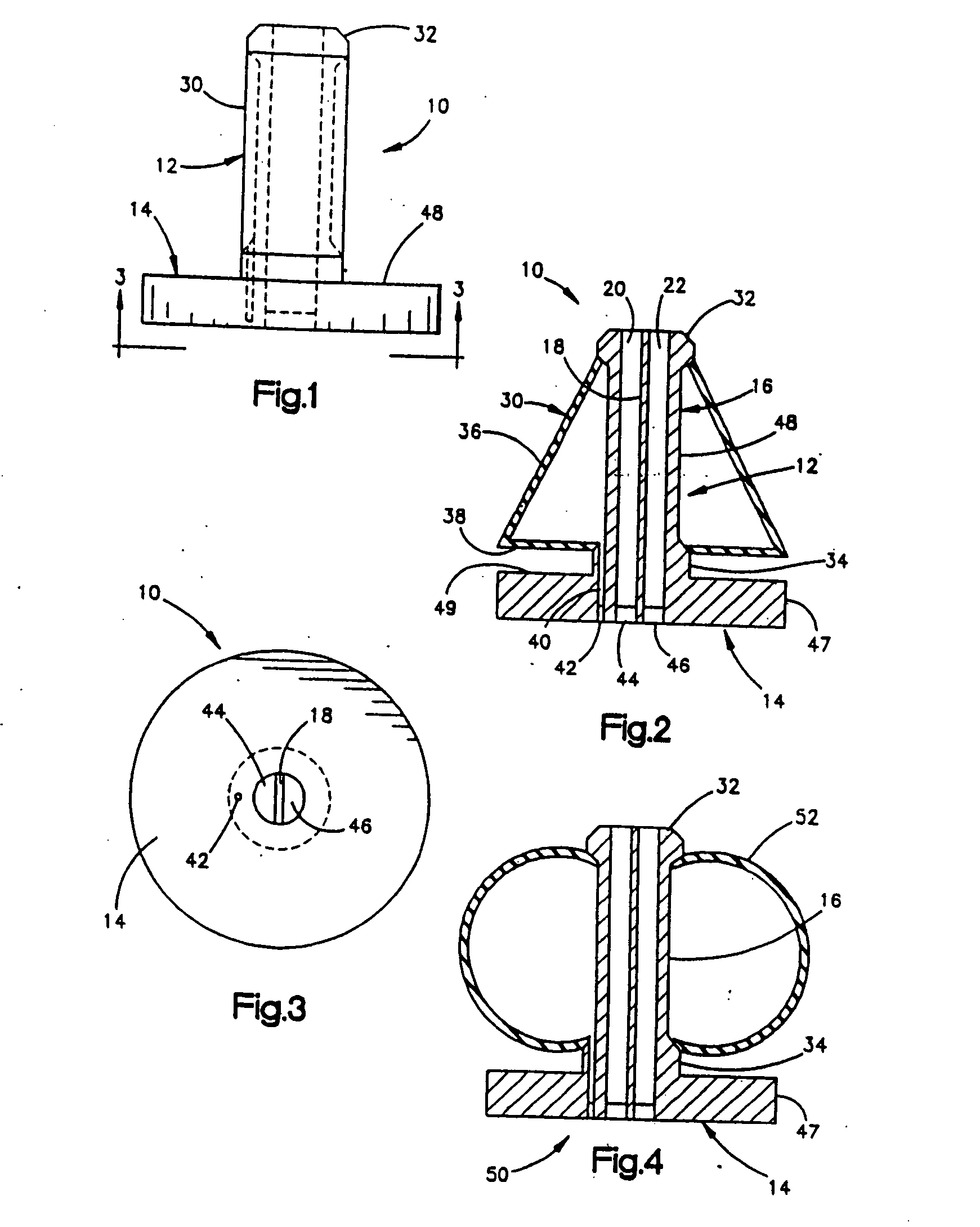
[0125]FIGS. 1-3 illustrate an arthritis irrigation apparatus 10. The irrigation system 10 includes a cannula 12 having a disc portion 14 and a longitudinally extending cannula body 16. A central wall 18 divides the cannula body 16 into two longitudinally extending lumens 20 and 22.

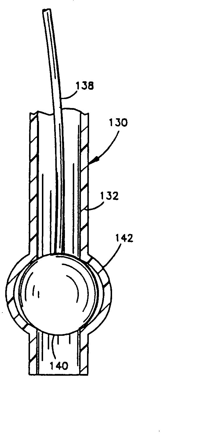
[0126] An expandable bladder 30 is connected to or formed integrally with the cannula 12 at the distal end 32 and proximal end 34 of the cannula body 16. The expandable bladder 30 includes a longitudinally extending wall portion 36 and a transversely extending wall portion 38. The expandable bladder 30 is supplied with fluid under pressure through a fluid supply port 40 closed by a rubber diaphragm seal 42. The lumens 20 and 22 are closed by similar diaphragm seals 44 and 46, respectively. The cannula body 16 has a recessed portion 48 in which the bladder 36 fits when unexpanded.

[0127] The system 10 is inserted into a pre-made opening until the disc portion 14 engages the skin. Upon the introduction of f...


PUM


Abstract

An active cannula which does more than merely maintain a passage is usable to create and / or enlarge a passage, to position a scope or instrument, to move or locate tissue, etc. The cannula can vary in size or shape as needed, intraoperatively. Because a cannula of the present invention is expandable, the surgeon can make a relatively small incision, stretch the tissue with the expandable cannula, contract the cannula and remove it, allowing the skin to come back to its unstretched condition. Thus, a smaller incision can be made to fit the same size instrument. The cannulas can assume such a non-circular shape, to fit into a natural skin opening and cause less trauma. The devices can be used to seal off a space, expand an existing space or a potential space for working or visualization, move tissue (for example, to stretch an incision), or protect tissue.

Description

RELATED APPLICATIONS [0001] This application is a continuation of co-pending U.S. application Ser. No. 10 / 099,265 filed Mar. 14, 2002 which is a continuation of U.S. application Ser. No. 08 / 727,968 filed on Oct. 9, 1996, now U.S. Pat. No. 6,358,266, which is a divisional of U.S. application Ser. No. 08 / 462,420, filed on Jun. 5, 1995, now U.S. Pat. No. 6,171,299, which is a divisional of U.S. application Ser. No. 08 / 195,337, filed on Feb. 14, 1994, now U.S. Pat. No. 5,514,153, which is a continuation-in-part of U.S. application Ser. No. 07 / 792,730, filed on Nov. 15, 1991, now U.S. Pat. No. 5,295,994, and a continuation-in-part of U.S. application Ser. No. 08 / 054,416, filed on Apr. 28, 1993, now abandoned, which is a divisional of U.S. application Ser. No. 07 / 487,645 filed on Mar. 2, 1990, now U.S. Pat. No. 5,331,975. The benefit of the earlier filing date of aforementioned applications is hereby claimed. The specifications of the aforementioned applications are hereby fully and expre...

Claims


Application Information

Patent Timeline
Patent Type & Authority Applications(United States)
IPC IPC(8): A61M29/02A61B17/00A61B17/02A61B17/22A61B17/32A61B17/34A61B19/00A61F2/958A61M5/32A61M25/06
CPCA61B17/02A61M2025/006A61B17/025A61B17/320036A61B17/320725A61B17/3421A61B17/3439A61B2017/00535A61B2017/00557A61B2017/0256A61B2017/320048A61B2017/3486A61B2019/462A61M5/3286A61M25/06A61M25/1002A61M29/02A61B17/0218A61B2090/062
Inventor BONUTTI, PETER
Owner BONUTTI PETER
Why Eureka
Try Eureka