Cutting Machine and Method of Moving Cutting Head

a cutting machine and cutting head technology, applied in the field of cutting machines, can solve the problems of increasing the cost required to make the movement speed in the y-axis direction faster than the movement speed in the x-axis direction, and the increase in the cost required to increase the cutting speed is not inevitable, so as to achieve the effect of improving the throughput of the cutting machine and large increase in cos

Inactive Publication Date: 2008-03-20
KOMATSU IND CORP
View PDF8 Cites 45 Cited by
  • Summary
  • Abstract
  • Description
  • Claims
  • Application Information

AI Technical Summary

Benefits of technology

[0018] According to the present invention, cutting machine throughput can be improved without incurring a large increase in cost.

Problems solved by technology

As a result, the cost increase required to make the movement speed in the Y-axis direction faster than the movement speed in the X-axis direction is not that large.
Moreover, the movement speed of the cutting head when cutting (the cutting speed) can remain the same as conventionally, which renders the increase in cost required to increase the cutting speed not inevitable.

Method used


Image

  • Cutting Machine and Method of Moving Cutting Head
  • Cutting Machine and Method of Moving Cutting Head
  • Cutting Machine and Method of Moving Cutting Head

Examples


Embodiment Construction

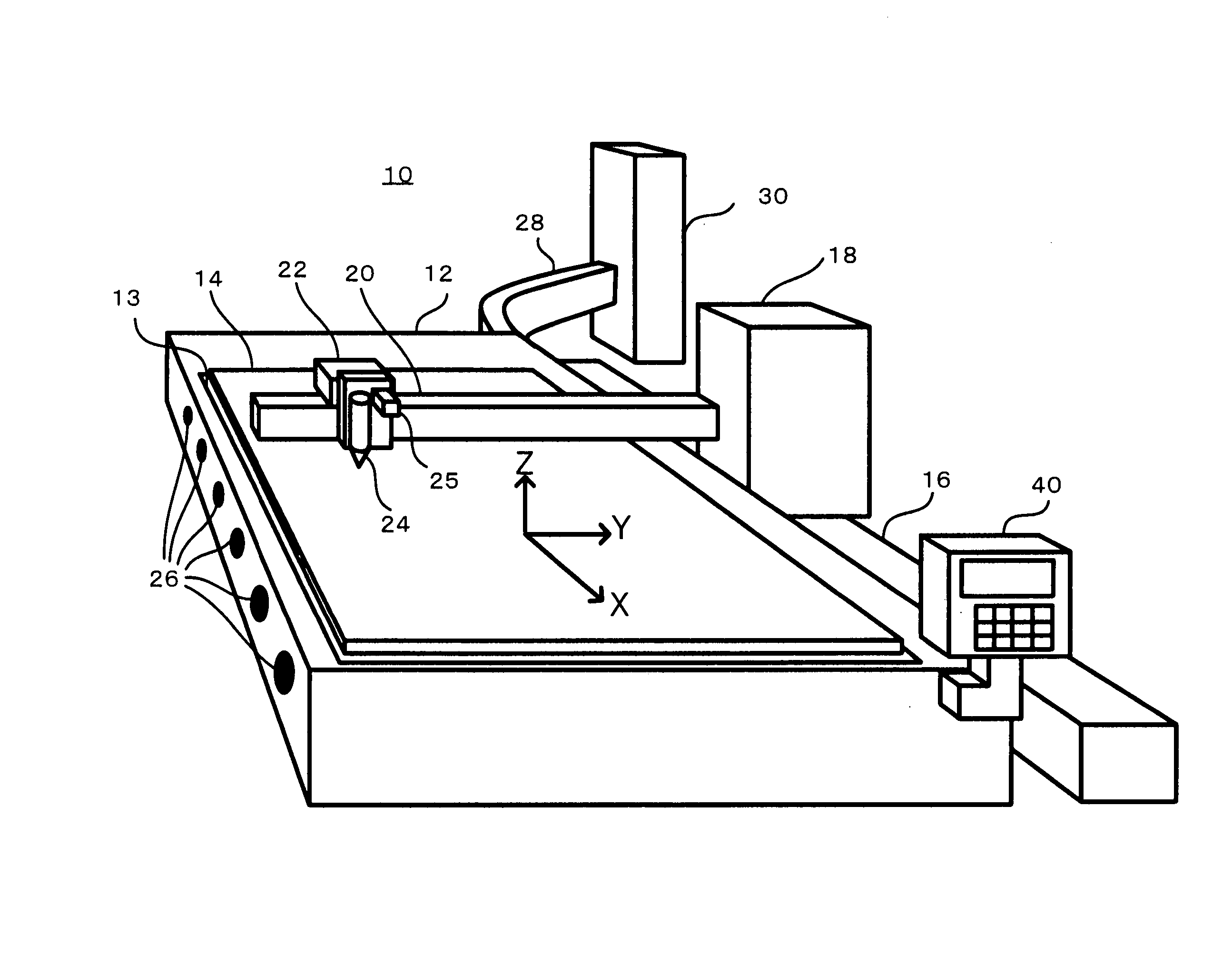
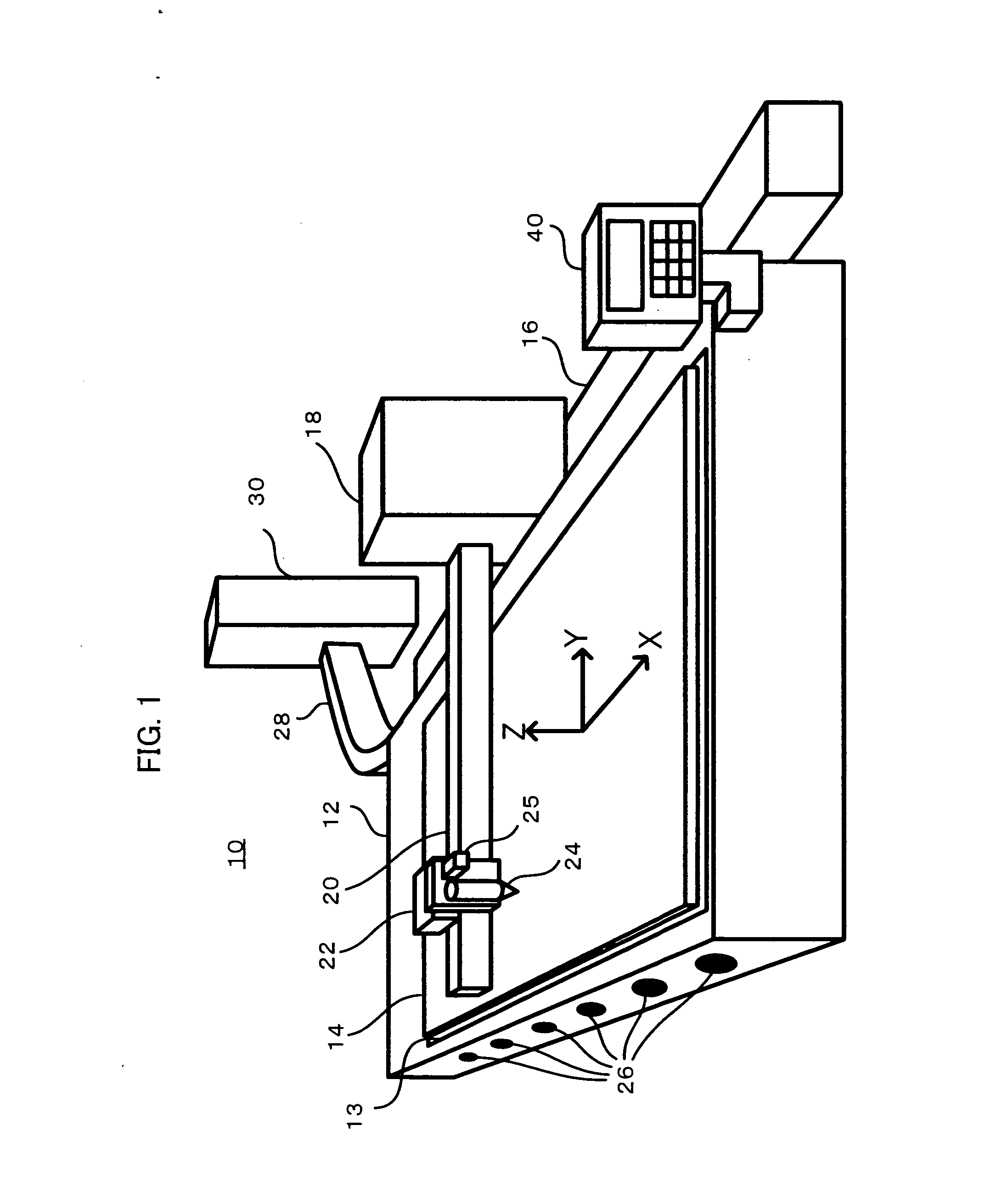
[0025]FIG. 1 is a perspective view showing the overall construction of a cutting machine according to the present invention.

[0026] As shown in FIG. 1, a cutting machine 10 comprises a box-like table 12 provided on the floor of the machine. A work area 13 is provide on the top surface of the table 12, and on this work area 13 a plate 14 that is the material to be cut is placed. In general, the plate 14 comes in rectangular standard sizes, such as 1.5 m×3 m or 2.4 m×6 m. The table 12 work area 13 is also a rectangular size suited to accommodate the particular standard sizes of the plate, and the table size, too, is a rectangular size that adds to the periphery of the work area 13 exhaust ducts and other such additional portions as are described later.

[0027] An X-Y-Z orthogonal coordinate system is defined for numerical calculation processing for the purpose of controlling the cutting position of the plate. The X axis of this X-Y-Z orthogonal coordinate system is parallel to the long...


PUM

PropertyMeasurementUnit
sizeaaaaaaaaaa
sizeaaaaaaaaaa
movement speedaaaaaaaaaa

Abstract

In a thermal cutting machine such as plasma cutting machine or a laser cutting machine, control of the moving speed of a cutting head (24) is improved so as to increase throughput of the cutting machine with increase in cost restricted. Products are cut out one by one from a plate member (14) while a cutting head (24) is moved relative to the plate member (14) on a table (12). In this process, when the cutting head (24) is fast-forwarded without performing cutting to a position at which cutting of each product starts, the speed of movement in the direction (Y-axis direction) along a short side of the table (12) is controlled at a speed higher than that of the movement in the direction (X-axis direction) along a long side of the table. The pattern of a sequence of cutting out the products from the plate member (14) is a meandering pattern in which reciprocation in the Y-axis direction dominates and the movement in the X-direction is one time one way. Exhaust chambers are arranged in the X-axis direction in the table (12), and the exhaust chambers are driven as the cutting head (24) moves in the X-axis direction.

Description

BACKGROUND OF THE INVENTION [0001] 1. Field of the Invention [0002] The present invention relates to a cutting machine that cuts a plate set on a table using a cutting head that moves over the surface of the plate and cuts out a product of a desired shape, and more particularly, to a technology that controls the movement speed of the cutting head in order to improve throughput. [0003] 2. Description of the Related Art [0004] As typical examples of the cutting machines of this type there are thermal cutting machines, such as plasma cutting machines that use a plasma torch as the cutting head, laser cutting machines that use laser torches, and gas cutting machines that use gas burners. A movement mechanism improved so as to lighten the machinery that moves the laser torch or the plasma torch in order to simplify cutting speed control and improve cutting accuracy is disclosed in JP-H7-108395-A. Efficiently exhausting fumes generated in the table during cutting by providing a plurality ...

Claims


Application Information

Patent Timeline
Patent Type & Authority Applications(United States)
IPC IPC(8): B26D5/02B23K26/08B23K7/10B26D1/00B26D5/00B23K7/00B23K10/00B23K26/00B23K26/082B23K26/10B23K26/16B23K26/38
CPCB23K7/002G05B2219/49074B23K10/00B23K10/006B23K26/0876B23K26/1405B23K26/38B23K26/422B23K37/006B23K2201/18B23Q15/08F16P3/14G05B2219/43124G05B2219/45044B23K7/10F16P3/141F16P3/144F16P3/147B23K26/702B23K26/142B23K2101/18Y10T83/8726Y10T83/081Y10T83/05B23K26/03B23Q5/28B23K37/0288G05B19/04
Inventor YAMAGUCHI, YOSHIHIROOHNISHI, SATOSHI
Owner KOMATSU IND CORP
Why Eureka
Try Eureka