
Efficient detection for ion traps

a technology of ion traps and ion traps, which is applied in the field of resonance ejection scan, can solve the problems of significant increase in instrument complexity and manufacturing cost, adversely affecting sensitivity, and loss of about half of detectable ions, and achieve significant cost savings and efficient detection

Inactive Publication Date: 2008-03-20
THERMO FINNIGAN
View PDF10 Cites 8 Cited by
  • Summary
  • Abstract
  • Description
  • Claims
  • Application Information

AI Technical Summary

Benefits of technology

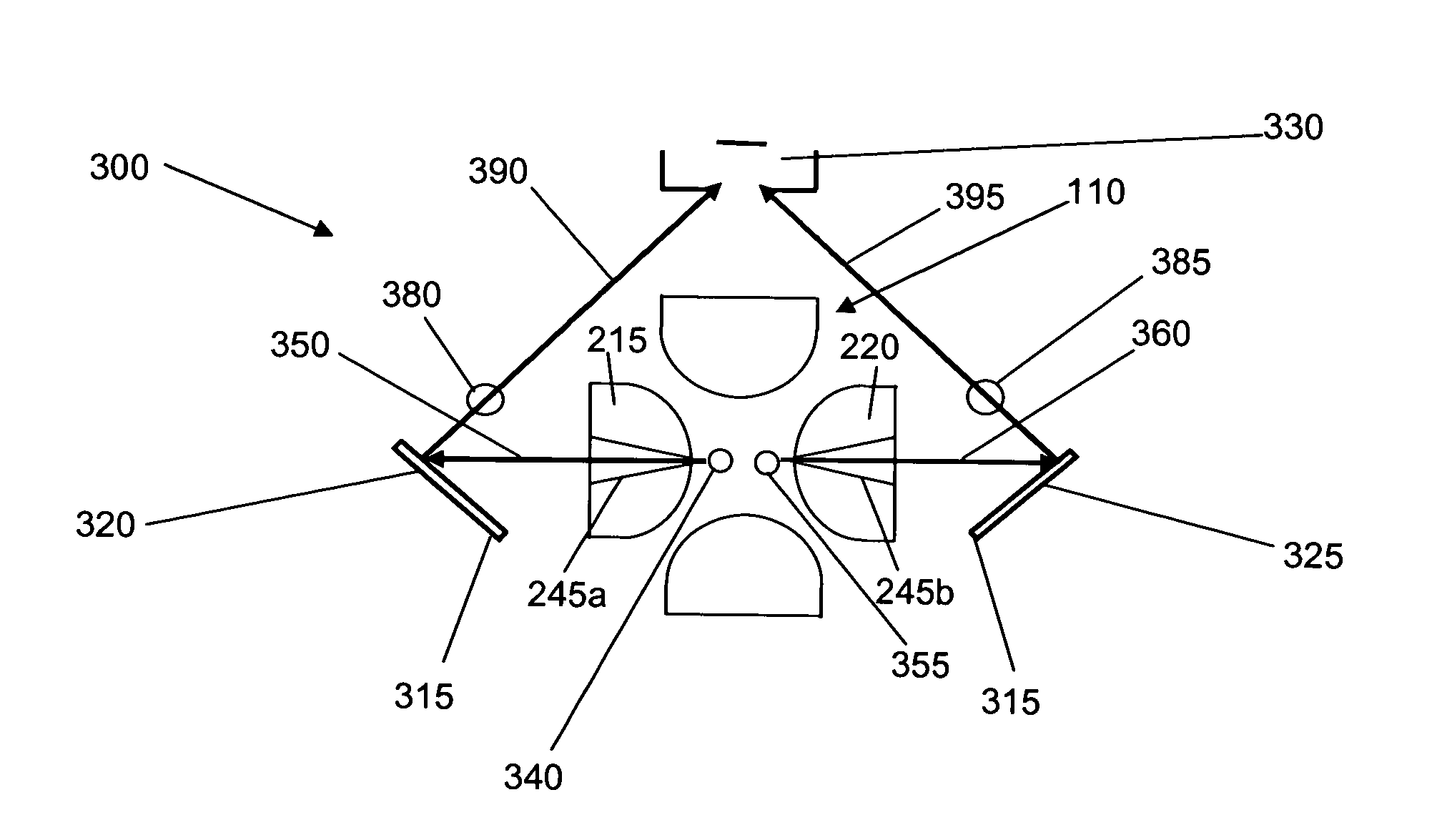
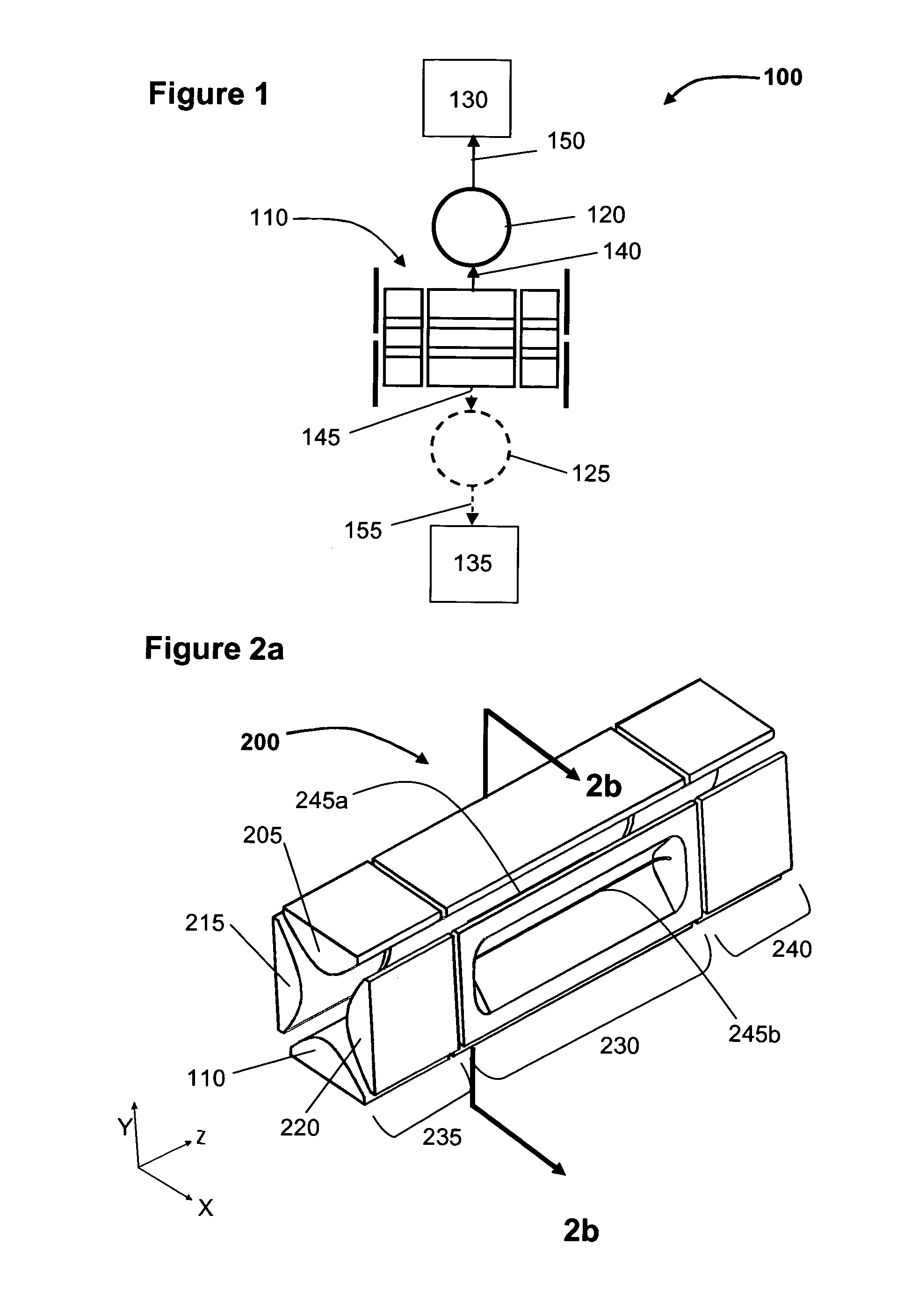
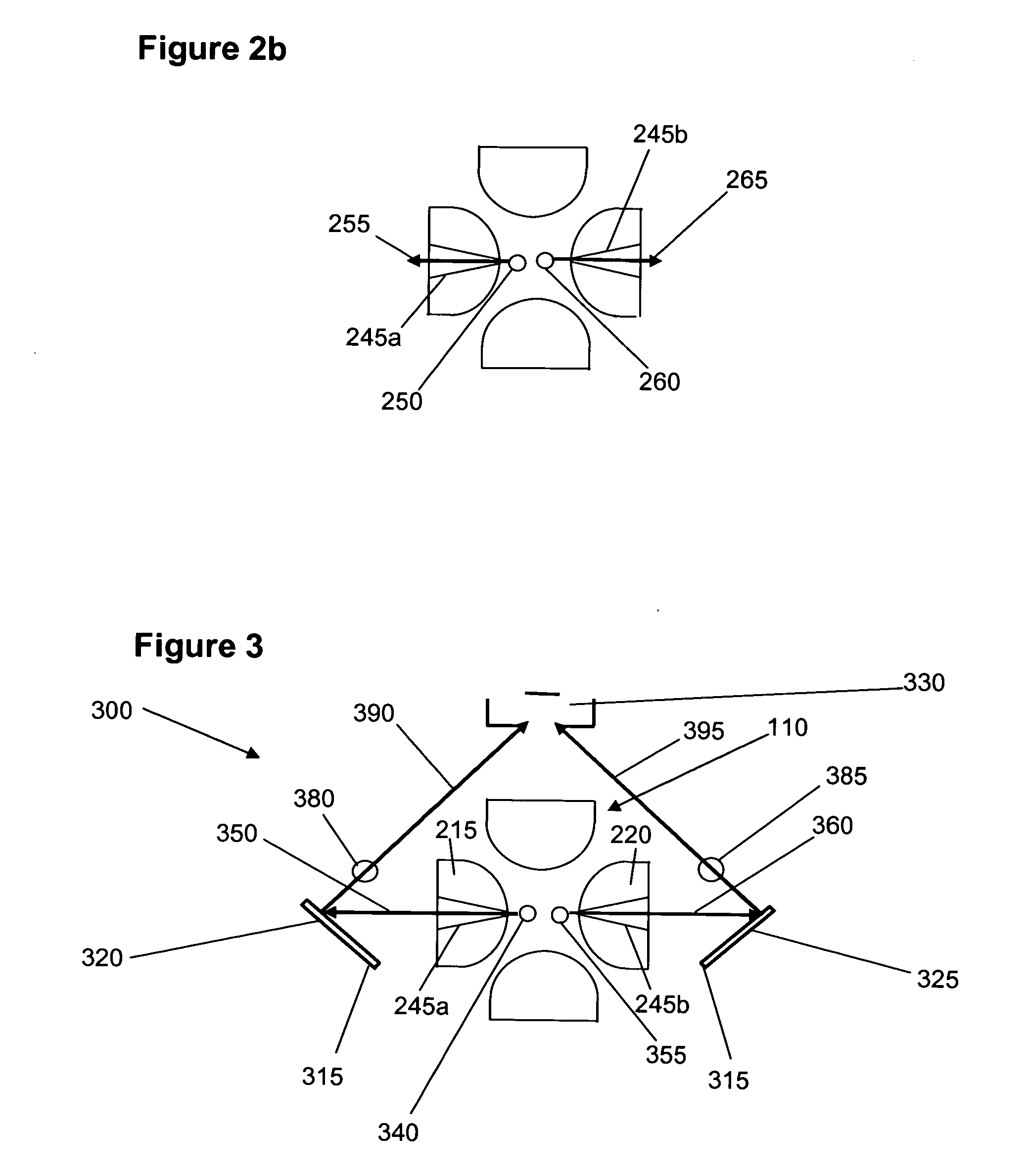
[0006]In accordance with one aspect of the present invention, an apparatus and method are disclosed that allows for efficient detection of ions ejected from a quadrupolar ion trap, such as a two-dimensional ion trap. The quadrupolar ion trap is conventionally configured to eject at least first and second groups of ions, the first group of ions being ejected in a direction different from the second group of ions. The first and second groups of ions travel on paths that terminate at an ion conversion dynode structure, which may be a common dynode or may consist of first and second dynodes (or sets of dynodes), each of which is positioned to receive a corresponding one of the ion groups. The secondary particles emitted from the ion conversion structure are subsequently directed to a shared detector, which responsively generates a signal representative of the numbers of secondary particles incident thereon, which in turn represents the combined number of ions in the first and second groups. In some implementations of the invention, the dynode structure is configured to perform an energy-filtering function, by which a significant portion of non-resonantly ejected ions travel on paths that do not result in the production of detectable secondary particles. Significant cost savings may be achieved by eliminating the need to provide a second detector.

Problems solved by technology

However, because only those ions that exit the trap through one of the apertures are detected (the other aperture is employed for ion injection) about fifty percent of the ejected ions are lost, thereby adversely affecting sensitivity.
However, the inclusion of two separate dynode / detector arrangements can significantly increase the instrument complexity and manufacturing cost, particularly since each dynode / detector arrangement and its associated components typically require a dedicated power supply of significant expense.
Of course, the cost of the instrument may be reduced by eliminating one of the dynode / detector arrangements and detecting only those ions that are ejected through one of the slots, but this configuration results in the loss of about half of the detectable ions and consequently produces a reduction in overall sensitivity of about 50 percent.

Method used


Image

  • Efficient detection for ion traps
  • Efficient detection for ion traps
  • Efficient detection for ion traps

Examples


Embodiment Construction

[0017]FIG. 1 schematically illustrates a typical two-dimensional linear quadrupolar ion trap system 100 according to the prior art. The system 100 comprises a linear quadrupolar ion trap 110, a conversion dynode 120, and an associated detector 130. The combination of the conversion dynode 120 and the detector 130 enable a parameter indicative of the number of ions ejected from one side of the linear ion trap 110 to be measured. Also illustrated in dotted lines is an additional combination of second conversion dynode 125 and second detector 135, which enable ions ejected from the other side of the linear ion trap 110 to be detected. As illustrated, each detector 130, 135 typically comprises an electron multiplier and a detector circuit. In general, the conversion dynodes, electron multipliers and detector circuits are powered by their own discrete power supplies. A single detector circuit can be utilized to detect the charged particles emanating from the two electron multipliers, but...


PUM


Abstract

An apparatus and method are disclosed for efficient detection of ions ejected from a quadrupolar ion trap, in which the ions are ejected as first and second groups of ions having different directions. The first and second groups of ions are received by a conversion dynode structure, which responsively emits secondary particles that are directed to a shared detector, such as an electron multiplier. The conversion dynode structure may be implemented as a common dynode or as two dynodes (or sets of dynodes), with each dynode positioned to receive one of the groups of ions.

Description

[0001]FIELD OF THE INVENTION[0002]The disclosed embodiments of the present invention relate generally to the field of mass spectrometers and more specifically to methods and apparatus for detecting ions ejected from a quadrupolar ion trap.BACKGROUND OF THE INVENTION[0003]The resonant ejection scan is a well-known technique for performing mass analysis in an ion trap mass spectrometer. Generally described, the resonance ejection scan utilizes a supplemental oscillatory voltage applied across opposing electrodes of the ion trap. As the main trapping voltage is ramped, ions are brought into resonance in order of their mass-to-charge ratios. The amplitude of motion of the resonantly excited ions increases in the dimension defined by the opposing electrodes until the ions either strike the electrode surfaces or are ejected from the trap through one or more apertures aligned with the dimension of excitation. In a three-dimensional quadrupolar ion trap, resonantly excited ions are ejected ...

Claims


Application Information

Patent Timeline
IPC IPC(8): H01J49/42
CPCH01J43/02H01J49/427H01J49/025H01J49/0095
Inventor SENKO, MICHAEL W.QUARMBY, SCOTT T.GUCKENBERGER, GEORGE B.
Owner THERMO FINNIGAN
Learn More