Hypodermic Injection System

a hyperdermic injection and high-speed technology, applied in the field of injectors, can solve the problems of many problems to be contended, body present difficulty in effective injection, and disclose the use of hubs from which the perforator shaft extends

Active Publication Date: 2008-03-20
MARK ANDERSON & ASSOCS
View PDF20 Cites 30 Cited by
  • Summary
  • Abstract
  • Description
  • Claims
  • Application Information

AI Technical Summary

Benefits of technology

[0012] An object of the present invention is to provide a well-controlled hypodermic injection system wh...

Problems solved by technology

Furthermore, there are many problems to be contended with.
Many bodies present difficulty in making effective injections due to the hair or fur, hair follicles, skin thickness, age of the species, their environment, etc.
While the importance and effectiveness of perforator delivery is clearly described in these prior art systems, they did not disclose the use of hubs from which the perforator shaft extends, which is different from hubs for standard needles, to totally prevent the use of standard needles whose length can reach 1.5 inches.
The prior art did not deal with the issue of long needles that often bend, and even break, an event that sometime leaves a needle in the consumable portion of the animal, not to mention the pain to the animal or the scarring/abscesses they cause deep in the muscle, or the economic loss they incur to the producers.
Another problem particularly prevalent in animals is the likelihood of sudden movement just prior to or during an injection.
No device has heretofore been available for disabling an injection if sudden movement occurs in the animal being injected, an event that could lead to a faulty injection that is both ineffective and damaging to the animal.
Also, no device has heretofore been available where the perforator assembly is attached ...

Method used


Image

  • Hypodermic Injection System
  • Hypodermic Injection System
  • Hypodermic Injection System

Examples


Embodiment Construction

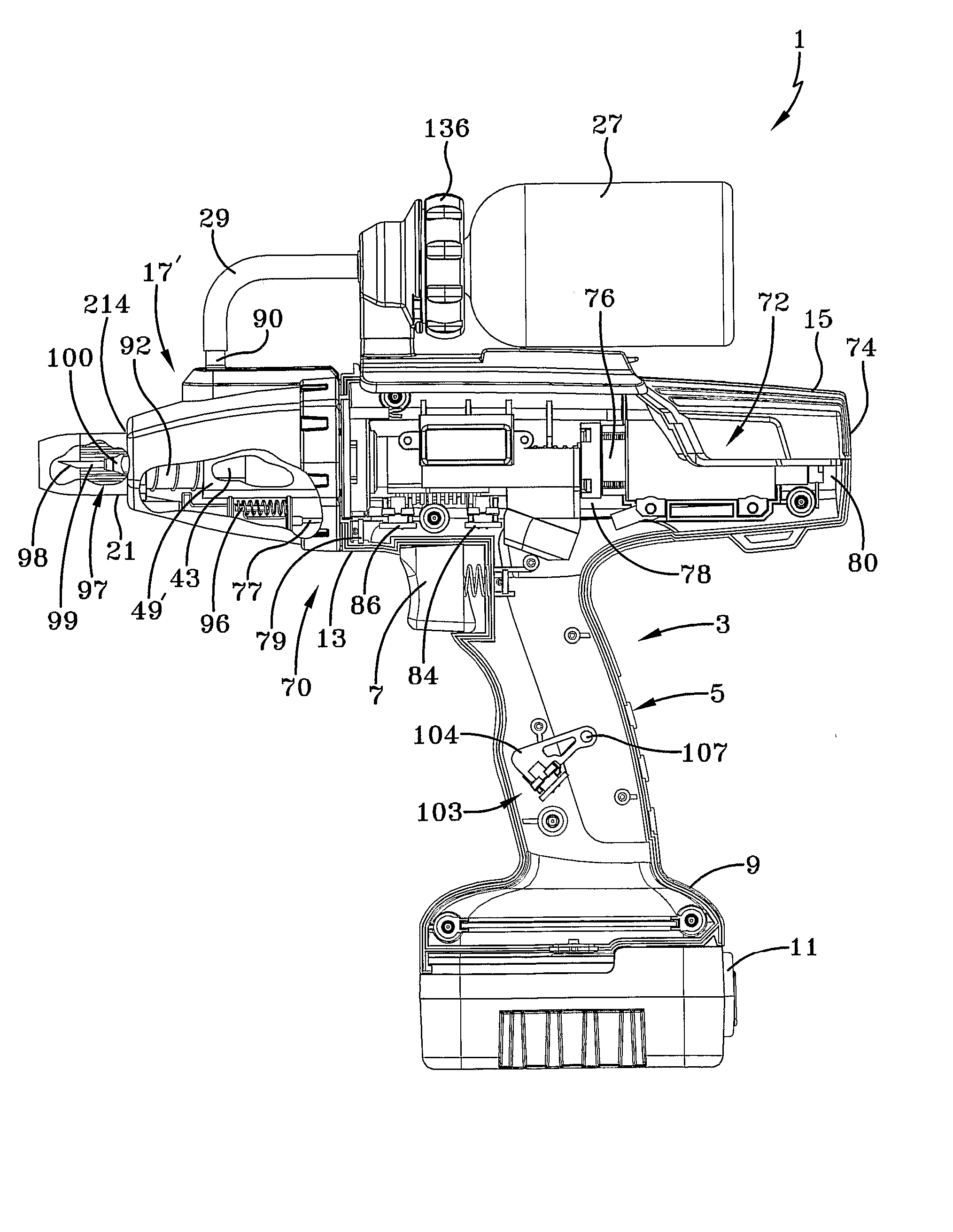
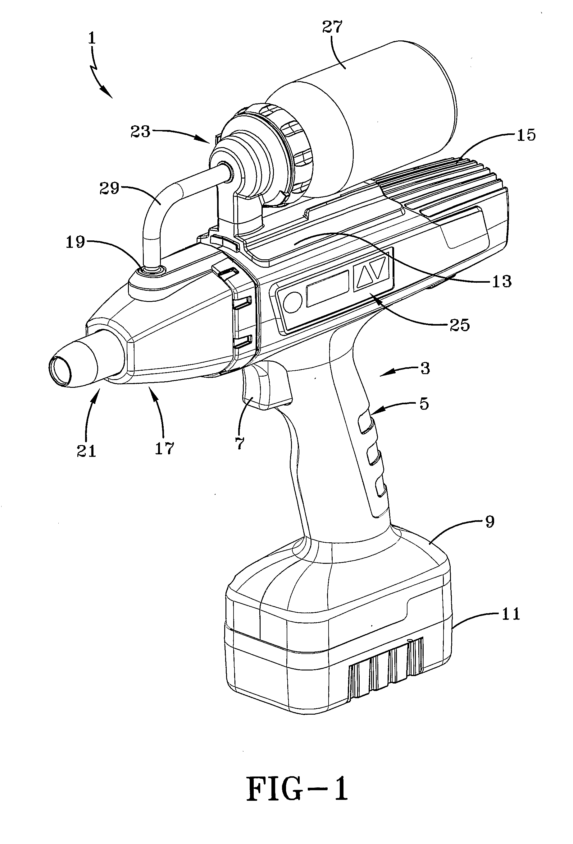
[0064] Turning first to FIG. 1, a hypodermic injection system 1 according to an embodiment of the invention is shown. System 1 includes a housing 3 for housing various items including a drive assembly discussed below. Housing 3 has a handle 5 with a finger trigger 7, a base 9 to which a battery 11 is attached, an upper portion 13 for holding a motor as described below and a motor heat sink 15, an injection head coupling assembly discussed below to which an injection head 17 is attached having an injectate input port 19 and a nose trigger or nose shield 21 (containing a contact trigger actuator discussed below), a bottle carriage assembly 23 and an input control selector and control display 25. A bottle or vial 27 for supplying injectate is shown attached to carriage assembly 23, and an output tube 29 runs from bottle 27 to injection input port 19.

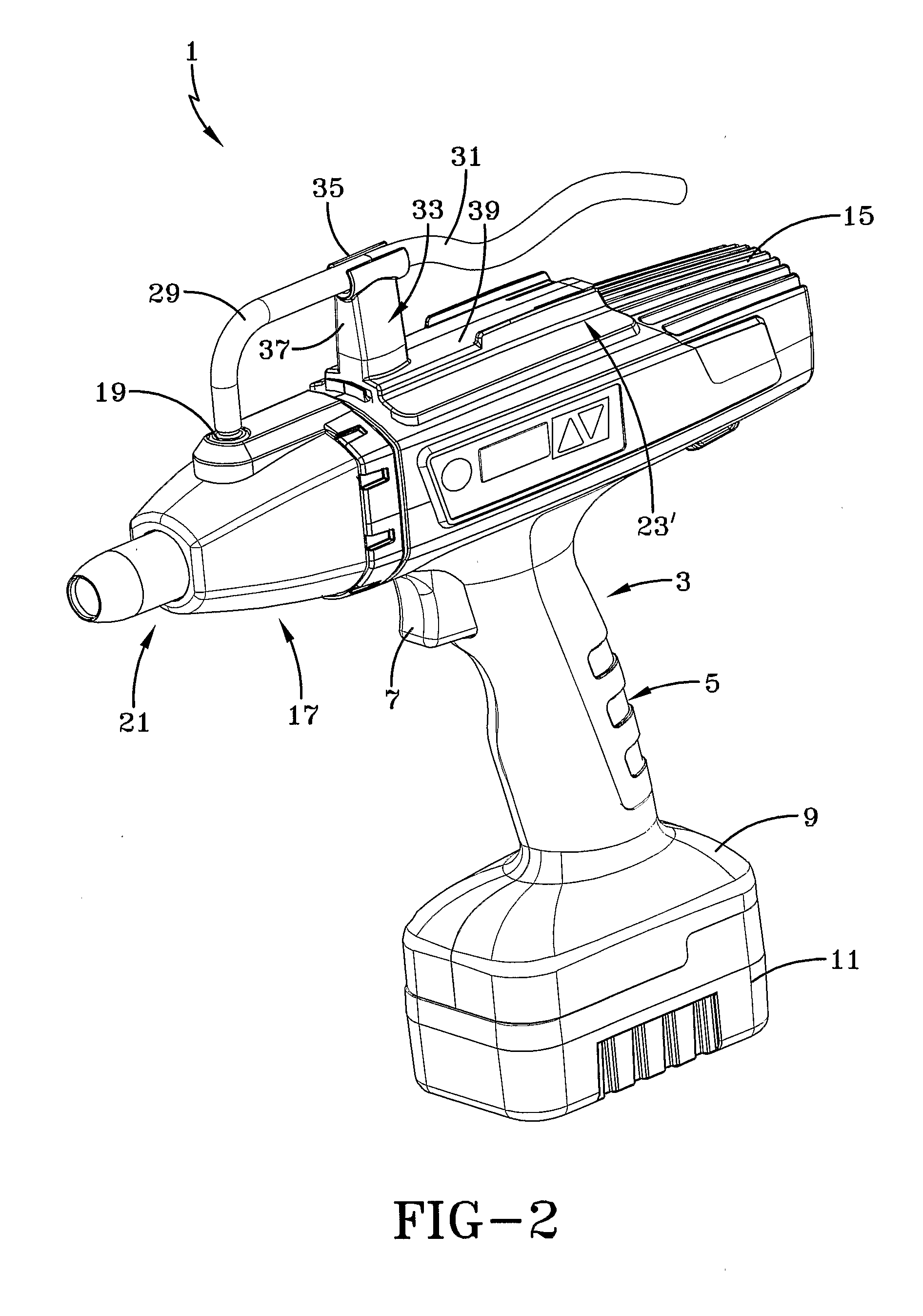
[0065]FIG. 2 shows hypodermic injection system 1, but in this case bottle 27 is replaced by a remote supply (not shown) from which a remo...


PUM


Abstract

The invention relates to a hypodermic injection system having a direct-drive motor for moving a ram towards an injectate chamber for discharging injectate therein through a discharge orifice. The system can have an injection head attached to a housing having an injectate chamber for holding injectate to be injected, a remote discharge device with a control apparatus or the structure for holding a cartridge containing injectate. The injectate supply could be a bottle, a remote reservoir or a cartridge. An injection head can have a nose actuator for enabling an injection only if the nose actuator has engaged the body to be injected. A clamping device clamps the body to be injected. Control is effected through a microprocessor to which the electrically-operated parts of the invention are attached. Control and output signals are readable through an electronic display.

Description

CROSS-REFERENCE TO RELATED APPLICATION [0001] This application claims benefit of U.S. provisional patent application Ser. No. 60 / 578,455 filed Jun. 9, 2004.BACKGROUND OF THE INVENTION [0002] 1. Field of the Invention [0003] This invention relates to injectors, and in particular to a high-speed hypodermic injection system for injecting animals or people at predetermined depths of injection with various safety features. [0004] 2. Description of the Prior Art [0005] Hypodermic injection systems have been developed for increasing the efficiency and effectiveness of injecting bodies of both animals and persons. Routine procedures against diseases and the possibility of pandemic or bioterror events makes the ability to have a high rate of injections very important in view of the vast numbers of injections to be made on herds of domestic animals such as cattle, goats, sheep, swine, chickens, turkeys and the like; water animals such as fish and shellfish including lobsters, shrimp, crabs an...

Claims


Application Information

Patent Timeline
IPC IPC(8): A61M5/20A61M5/00A61M5/32
CPCA61M5/008A61M5/204A61M5/30A61M2005/31588A61M5/31546A61M5/3205A61M2205/50A61M5/31525
Inventor D'ANTONIO, NICHOLAS F.D'ANTONIO, NICHOLAS J.COLVIN, RICHARD O.
Owner MARK ANDERSON & ASSOCS
Why Eureka
Try Eureka