System and method for microablation of tissue

a microablation and tissue technology, applied in the field of tissue laser treatment, can solve the problems of inability to treat many patients, inability to achieve the effects of reducing scars, reducing wrinkles, and reducing scars

Active Publication Date: 2008-03-20
LUMENIS LTD
View PDF42 Cites 20 Cited by
  • Summary
  • Abstract
  • Description
  • Claims
  • Application Information

AI Technical Summary

Benefits of technology

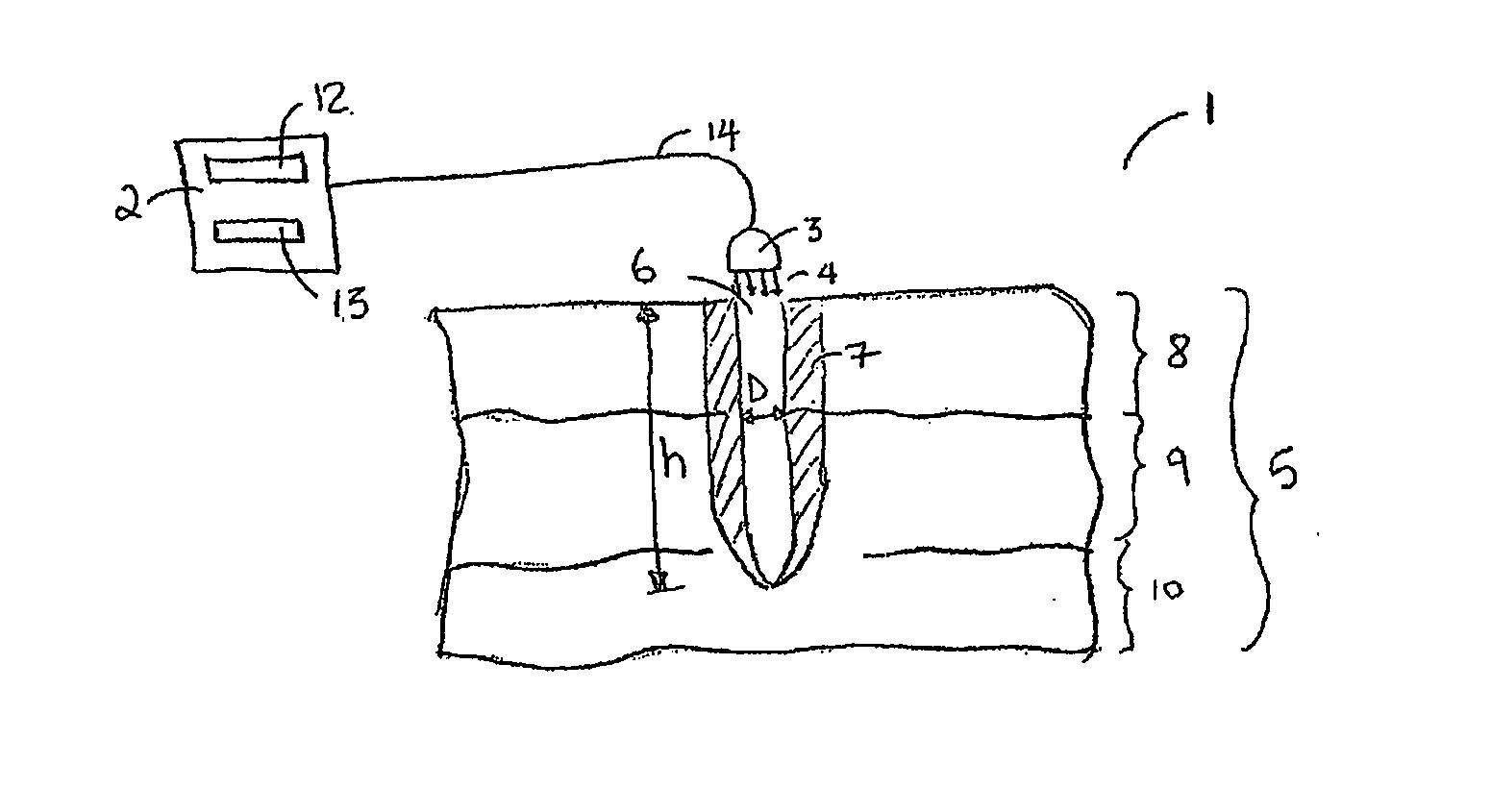
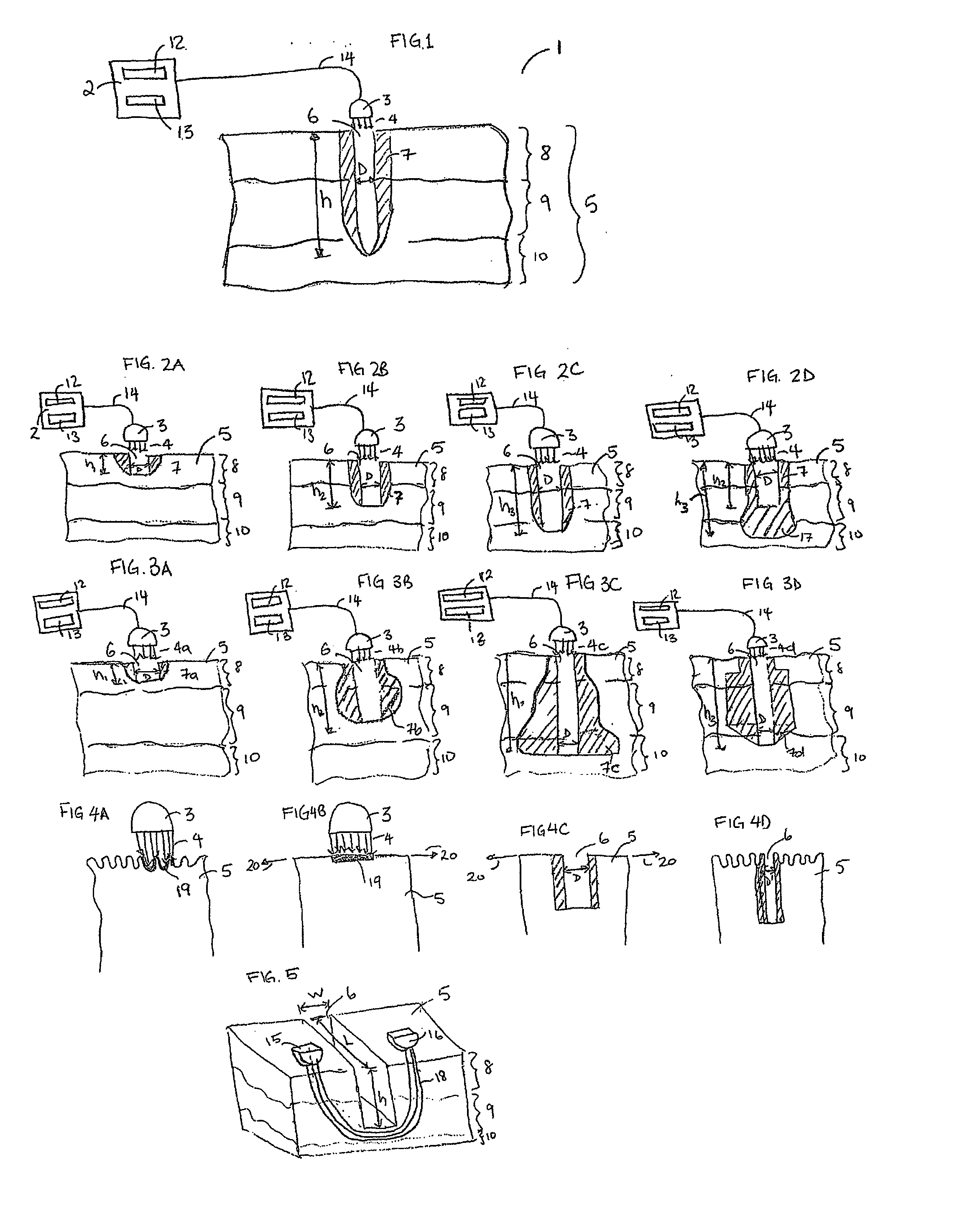
[0017] As will be appreciated by those persons skilled in the art, a major advantage provided by the present invention is full control of: depth of treatment, the amount and placement of heat, and the amount and placement of channels. It is therefore an object of the present invention to rejuvenate skin and reduce wrinkles, scars, dyschromia and other conditions such as melasma and hyperpigmentation. It is another object to provide a channel with or without heat for delivery other therapy (vitamins, drugs, etc). Additional objects of the present invention will become apparent from the following description.

Problems solved by technology

LSR generally may result in fairly extensive thermal damage to either the epidermis and / or the dermis.
Major drawbacks include, however, edema, oozing, and burning discomfort up to the first fourteen (14) days after treatment.
Such drawbacks are unacceptable for many patients.
A further problem with LSR procedures is that they are relatively painful.
Therefore, they generally require an application of a significant amount of analgesia.
While LSR of relatively small areas can be performed under local anesthesia, LSR procedures that include relatively large areas frequently require general anesthesia or nerve blockage by multiple anesthetic injections.
Another limitation of LSR is that ablative laser resurfacing generally can not be performed on the patients having dark complexions.
Ablation of pigmented epidermis tissue can cause severe cosmetic disfigurement to patients having a dark complexion.
This is generally considered to be unacceptable by most patients and physicians.
Yet another limitation of LSR is that ablative resurfacing generally has a greater risk of scarring in areas other than the face and result in an increased incidence of an unacceptable scar formation because the recovery from skin injury within these areas is not very effective.
This results in biological repair and the formation of new dermal collagen which in turn can result in decreased photoaging related structural damage.
Avoiding the epidermal damage by using NCR techniques may also decrease both the severity and the duration of treatment related side effects, for example, post procedural oozing, crusting, pigment changes, and the incidence of infections.
Further, when NCR techniques are used, they generally do not have the undesirable side effects characteristic of the LSR treatment, such as the risk of scarring or infection.
Although these NCR techniques may avoid epidermal damage, a major drawback of this method is its limited effectiveness.
In fact, even when multiple NCR treatments are employed, improvement in the patient's skin is often far below expectations.
In addition, improvement is often delayed for several months when a series of treatment procedures are used.
Although NCR techniques have been found to be moderately effective for wrinkle removal, they have generally not been found to be effective for dyschromia
Another problem with using a NCR technique is the limited the breadth of acceptable treatment parameters for safe and effective treatment of dermatological disorders.
This results in an unfavorable temperature profile in the skin.
An unfavorable temperature profile consequently results in either no therapeutic effect on one hand, or scar formation due to the overheating of a relatively large volume of the tissue, on the other.
A problem that is common to both ablative and non-ablative resurfacing procedures is that they do not significantly use keratinocytes, which play an active role in the wound healing response.

Method used


Image

  • System and method for microablation of tissue
  • System and method for microablation of tissue
  • System and method for microablation of tissue

Examples


example

[0056] It is to be understood that the following example of the present invention is not intended to restrict the present invention since many more modifications may be made within the scope of the claims without departing from the spirit thereof.

[0057] A study was conducted that consisted of two research criteria. The first criterion evaluated different laser energy doses on 47 consecutive samples of skin. The doses ranged from 5 m.T to 200 mJ. The width and depth of the ablated “column” was measured as well as the surrounding width and depth of necrosis. The second criterion compared the effects of doses ranging from 5 mJ to 20 mJ on the arms of selected volunteers. These evaluations were recorded immediately after the firing of the laser; at one hour; one day and four days.

[0058] Summary of Results or Findings

[0059] The depth and diameter of the ablated columns correlated in a linear fashion with the dose. The column depth could be directly controlled and ranged from 180 to 13...


PUM


Abstract

The present invention generally relates to the field of laser treatment of tissue, and particularly, to a system and method for creating microablated channels in skin. The present invention is more particularly directed to treating subsurface tissue through the created channels.

Description

CROSS REFERENCE TO RELATED APPLICATIONS [0001] This application claims the benefit of U.S. Ser. No. 60 / 791,194, filed on Apr. 12, 2006 (and entitled: System, Method and Apparatus For Laser Treatment of Tissue), U.S. Ser. No. 60 / 850,628, filed on Oct. 11, 2006 (and entitled: A Novel Microablative Device) and U.S. Ser. No. 60 / 832,964, filed on Jul. 25, 2006 (and entitled: System, Method and Apparatus For Laser Treatment of Tissue) which are incorporated in their entirety herein by reference.BACKGROUND OF THE INVENTION [0002] 1. Field of the Invention [0003] The present invention generally relates to the field of laser treatment of tissue, and particularly, to a system and method for creating microablated channels in skin. The present invention is more particularly directed to treating subsurface tissue through the created channels. By doing treating subsurface tissue through uniquely created channels, skin may be treated with heretofore unrealized results. [0004] 2. Description of the...

Claims


Application Information

Patent Timeline
Patent Type & Authority Applications(United States)
IPC IPC(8): A61B18/18
CPCA61B18/203A61B2017/00761A61B2018/00458A61B2018/00452A61B2017/00765
Inventor LEMBERG, VLADIMIREPSHTEIN, VITALIIGER, YONIPANNELL, JOHN
Owner LUMENIS LTD
Why Eureka
Try Eureka