

Plasma reactor
- Summary
- Abstract
- Description
- Claims
- Application Information
AI Technical Summary
Benefits of technology
Problems solved by technology
Method used
Image

Examples
example 1
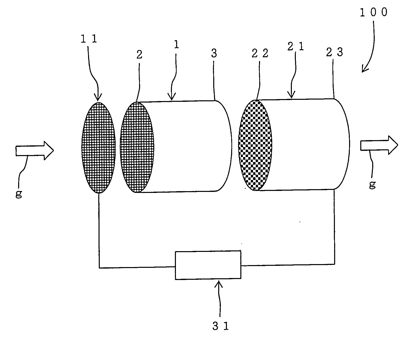
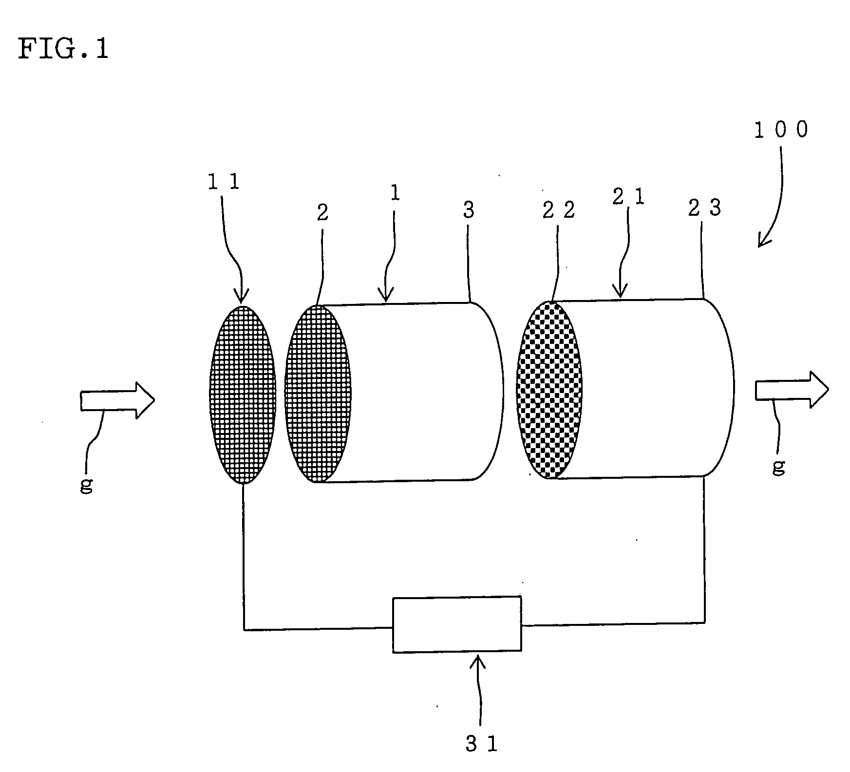
Plasma Reactor Main Body
Honeycomb Structure
[0057] A plasma reactor main body was produced by extruding cordierite as a raw material using a metal die so that the length in the exhaust gas flow direction was 5 mm, the diameter of the end face was 93 mm, the cell pitch was 2.5 mm, and the thickness of the partition wall was 0.43 mm, and then firing the resulting product.
[0058] Positive Electrode
[0059] A mesh-type electrode was used as the positive electrode. The positive electrode was formed of conductive members arranged in parallel in the vertical direction and the horizontal direction at intervals (5.0 mm) twice the cell pitch of the plasma reactor main body. The positive electrode was formed by punching a stainless steel sheet material.
[0060] Honeycomb Filter (DPF)
[0061] A silver paste was applied to and baked on the end face (filter outlet end) of an SiC-DPF (manufactured by NGK Insulators, Ltd., length in exhaust gas flow direction: 100 mm, diameter of end face: 93 mm, cel...
example 2
[0072] A plasma reactor was produced in the same manner as in Example 1 except for causing a catalyst (Pt / Al2O3) to be supported on the plasma reactor main body. The catalyst was supported on the plasma reactor main body using the following method. The exhaust gas purification test was carried out and the NOx concentration and the amount of deposited PM were measured in the same manner as in Example 1. The results are shown in Table 1.
[0073] Method of Supporting Catalyst on Plasma Reactor Main Body
[0074] Alumina fine powder (specific surface area: 100 m2 / g) was impregnated with a dinitrodiamine Pt aqueous solution, dried at 120° C., and fired at 550° C. for three hours to obtain Pt / alumina powder containing Pt in an amount of 10 mass % of the alumina. Alumina sol and water were added to the Pt / alumina powder to obtain a slurry. The plasma reactor main body was immersed in the slurry, dried, and fired to cause the catalyst to be supported on the surface of the wall of the plasma re...
example 3
[0075] A plasma reactor was produced in the same manner as in Example 2 except that a catalyst (Pt / Al2O3) was also supported on the honeycomb filter (DPF). The catalyst was supported on the honeycomb filter in the same manner as described in “Method of supporting catalyst on plasma reactor main body”. The exhaust gas purification test was carried out and the NOx concentration and the amount of deposited PM were measured in the same manner as in Example 1. The results are shown in Table 1.
PUM
| Property | Measurement | Unit |
|---|---|---|
| Length | aaaaa | aaaaa |
| Length | aaaaa | aaaaa |
| Electric potential / voltage | aaaaa | aaaaa |
Abstract
Description
Claims
Application Information