If the external
heat energy introduced into the biomass material is at a very high temperature or is applied very abruptly, especially in a concentrated area, then two things tend to happen: Firstly, any reactions that occur tend to be rather violent, thus causing the production of fly-ash into the fumes of the volatilizing biomass; secondly, the sudden and concentrated reactions produce a large amount of
heat energy, which in turn can cause the abrupt volatilization of the surrounding material, which volatilization can be somewhat violent.
Further, if a substantial amount of material is volatilized, in the manner discussed immediately above, over a relatively short period of time, then the ambient temperature of the primary chamber will tend to rise substantially, thus causing the remaining biomass to be volatilized more quickly, but not at a controlled rate.
In other words, the reaction is, at least to some degree, out of control.
It is found, however, that the fumes that are driven off contain a great quantity of materials, such as fly-ash, having
hydrogen-carbon bonds, and other unincinerated materials.
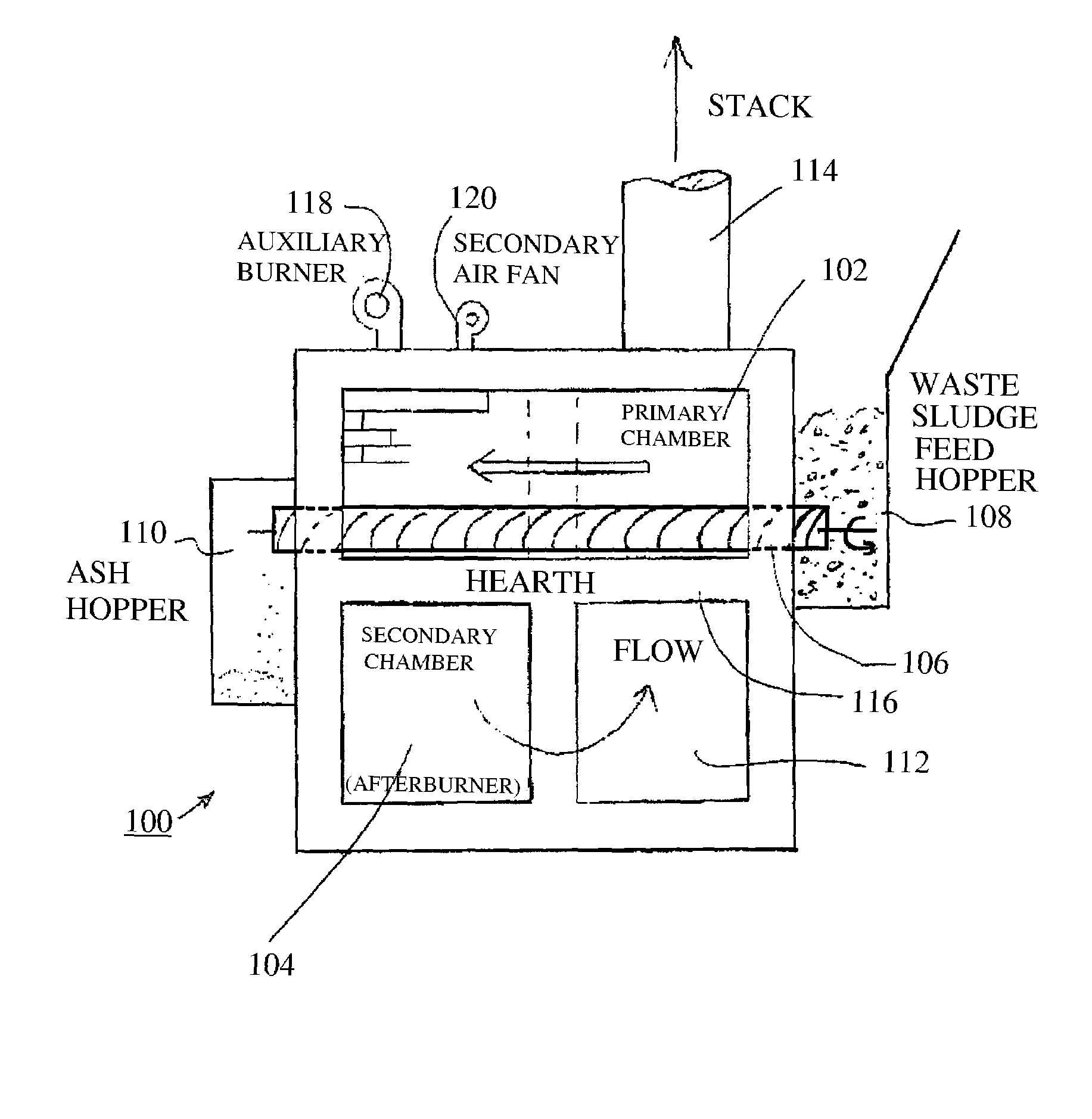
However, relatively large pieces of material, such as fly-ash, may contain several million or billion molecules; and, accordingly, such pieces of material as are borne by the fumes may not get fully incinerated in the time that they take to pass through the afterburner chamber 7.
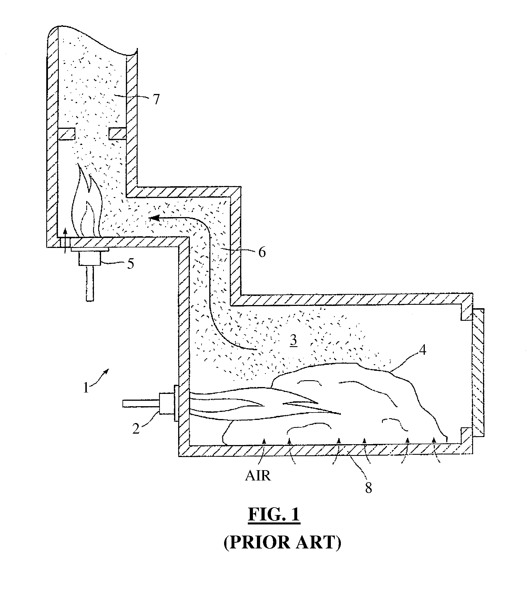
The
flame tends to cause the biomass waste to inflame and also tends to physically agitate the biomass 4.
As a result, an undesirably high amount of fly-ash is included within the fumes from the burning biomass 4.
Further, this type of conventional prior art incinerator 1 does not provide sufficient heat intensity on an overall basis to properly incinerate all of the
waste material.
There is often not enough heat intensity to cause complete gasification even of the materials that do burn, and certainly not enough heat intensity to cause complete gasification of the
waste material at the centre of the biomass.
It has been found that typically there is also undesirable material such as dioxins, furans and organo-chlorides, and other
organic matter.
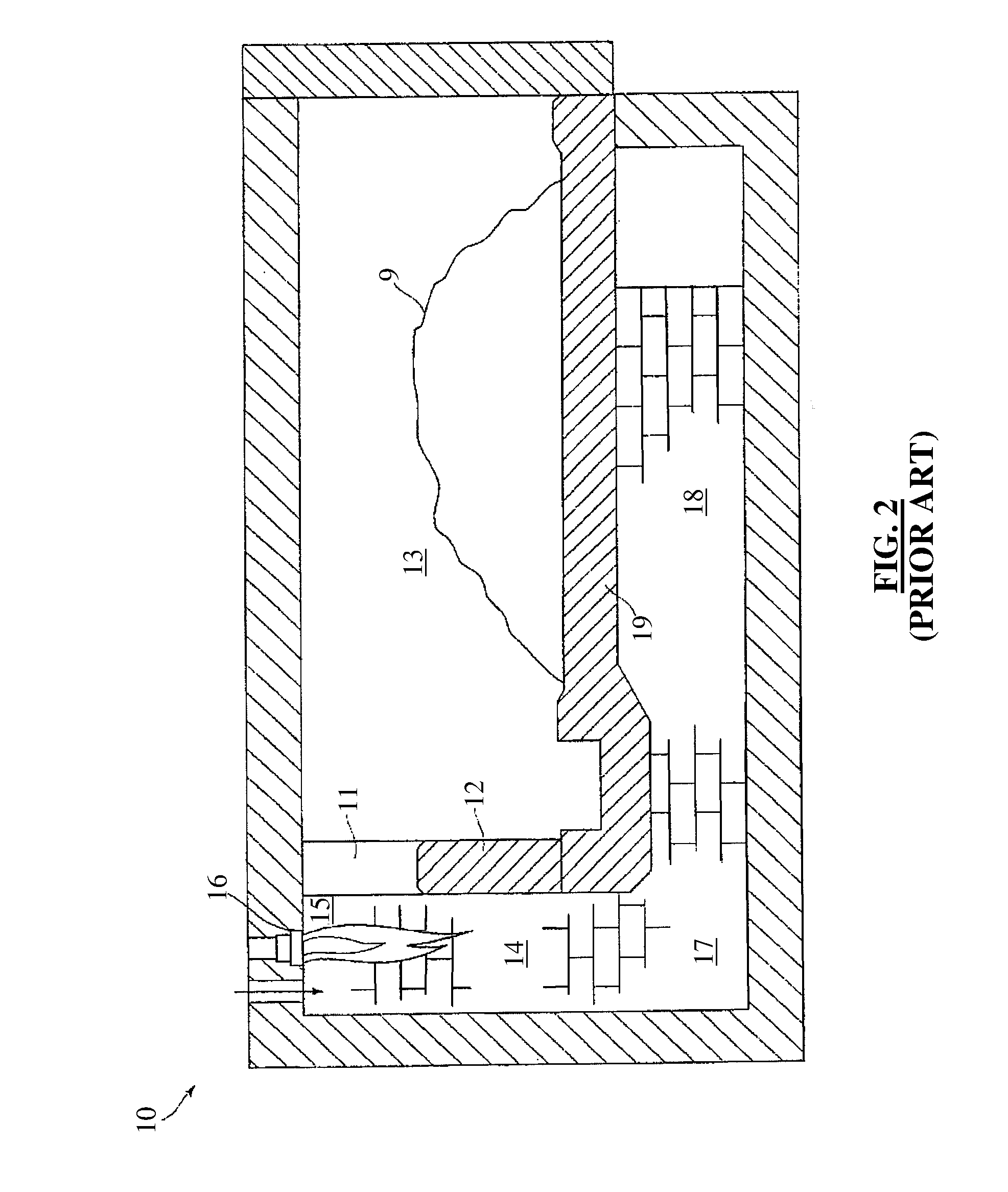
Such
incineration by way of direct
radiant heat tends to cause burning of the biomass 9 so as to cause premature ignition which leads to incomplete
combustion in the early stages of the process.
The firing of this burner can cause
instability in the primary chamber and cause the emission of fly-ash material.
Such incomplete gasification is generally unacceptable as this material might include hydro-carbons, dioxins, furans, and other unwanted
organic matter such as
bacteria, viruses, and other micro-organisms.
It has been found that the use of such multiple control systems tends to produce an overall
system wherein the temperature in the primary chamber may vary and, therefore, cannot be considered stable.
Such lack of stability is caused by the plurality of control systems essentially working against each other.
It has been found that such prior art incinerators and cremators as discussed above, due to the inherent nature of the
incineration process that occurs, produce an unacceptable end product.
The fumes that are produced have relatively high levels of hydro-carbons, dioxins, furans, among other materials and substances, and also may contain fly-ash, while the resulting ash remaining in the incinerator may have unwanted
organic matter such as
bacteria, viruses, and other microorganisms.
It can therefore be seen that
incineration of biomass waste and related volatile solids is generally unacceptable as it does not render potentially infectious waste totally safe.

