Calibrated microelectromechanical microphone

a micro-electromechanical and microphone technology, applied in the direction of transducer details, electrostatic transducer microphones, electrical transducers, etc., can solve the problems of significant disadvantages of well-controlled mems microphone fabrication, mems microphones impose severe limitations on how a dc bias voltage can be adjusted, and the production yield of mems microphones may be increased. , the effect of maximizing the sensitivity of individual microphones

Active Publication Date: 2008-03-27
TDK CORPARATION
View PDF11 Cites 119 Cited by
  • Summary
  • Abstract
  • Description
  • Claims
  • Application Information

AI Technical Summary

Benefits of technology

[0020]By using a programmable DC bias-voltage generator, the production yield of the MEMS microphones may be increased, while at the same time the sensitivity of individual microphones may be maximized.
[0021]As an example, the DC bias-voltage of the MEMS transducer element could be controlled to be between 5 and 10 Volts, depending on the stiffness of the diaphragm. Furthermore, the DC bias-voltage could be maximized without risking diaphragm collapse during normal operating conditions. This will result in better sensitivity and lower noise of the MEMS microphone assembly. Typically, the DC bias-voltage would not be changed continuous...

Problems solved by technology

A significant problem in producing MEMS condenser microphones with high yield is that the compliance or tension of the MEMS microphone diaphragm varies according to a number of manufacturing parameters that are difficult to accurately control.
This is a significant disadvantage for well-controlled MEMS microphone fabrication.
The small dimensions of MEMS microphones impose severe limitations on how a DC bi...

Method used


Image

  • Calibrated microelectromechanical microphone
  • Calibrated microelectromechanical microphone
  • Calibrated microelectromechanical microphone

Examples


Embodiment Construction

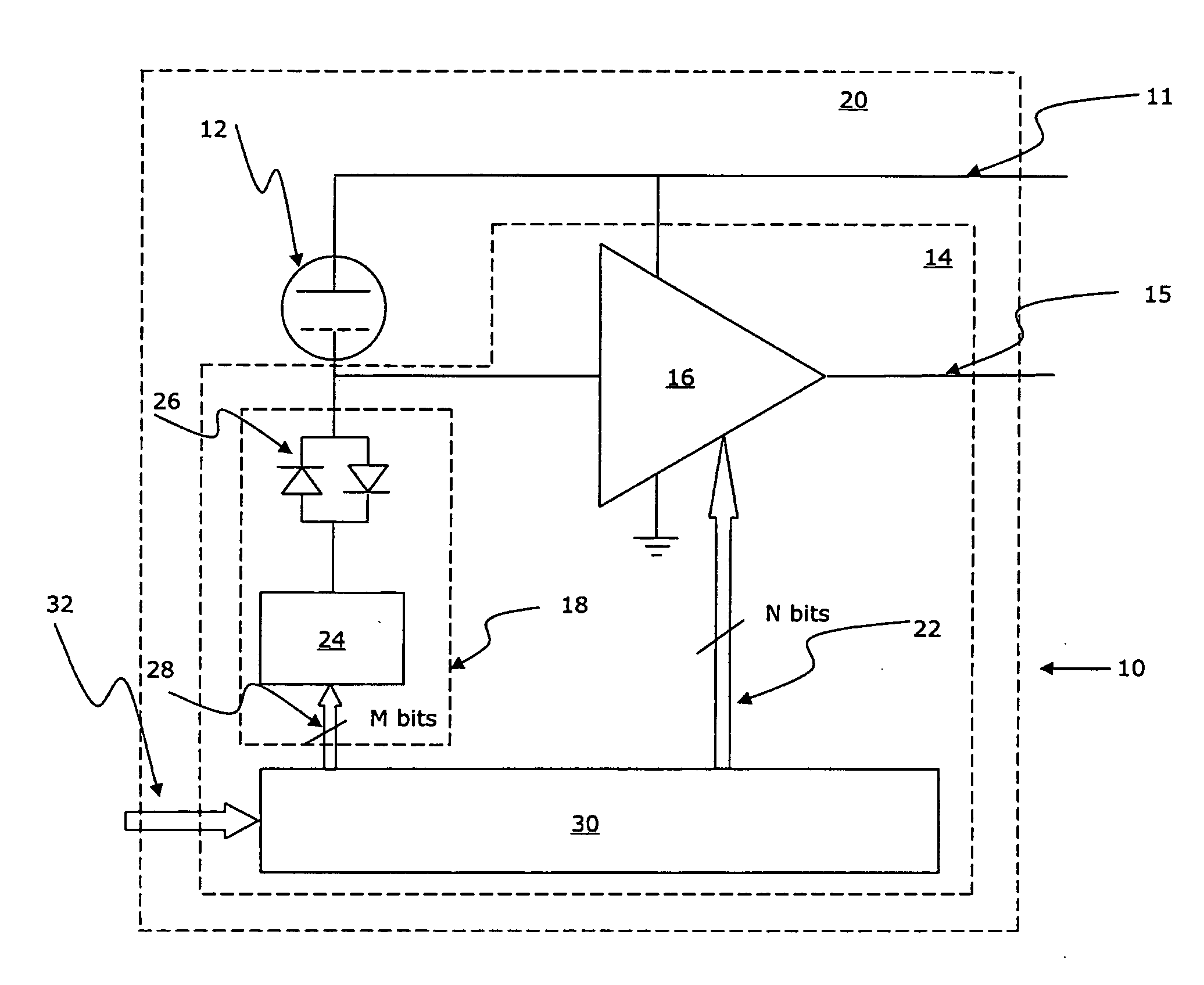
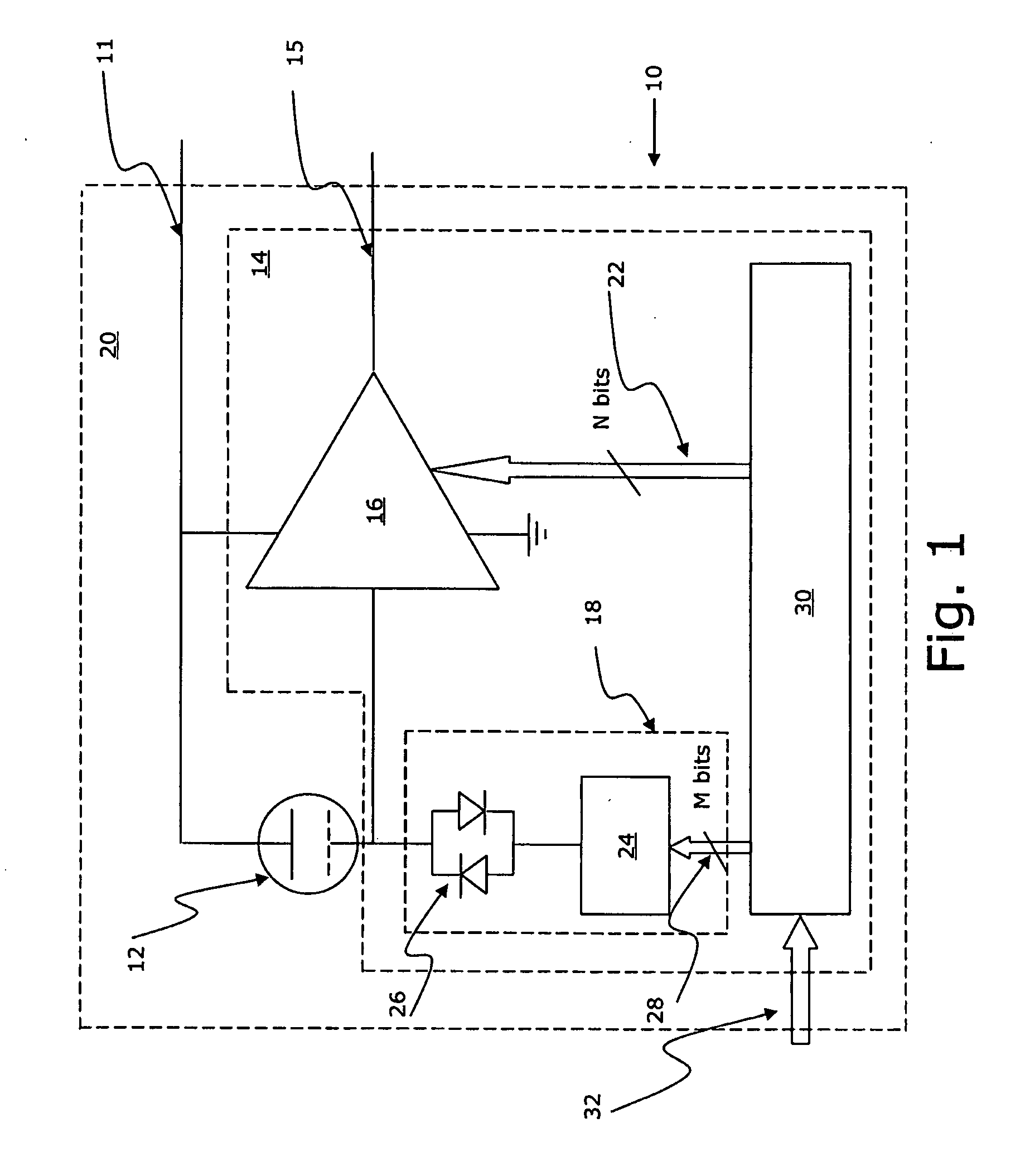
[0062]The preferred embodiment of a microphone 10 of the invention comprises a MEMS condenser microphone / transducer 12 with an integrated circuit portion 14 which comprises a microphone (pre)amplifier 16, a DC bias voltage generator 18 and is built into a microphone housing / package 20. In addition, the microphone has a voltage supply 111 and an output 15.

[0063]The amplifier 16 comprises an input for data 22 for adjusting the gain thereof, and the bias voltage generator 18 comprises a diode set-up 26 and a Dickson pump 24 (see e.g. EP-A-1 599 067 which is herein incorporated by reference in its entirety) having an input for data 28 for regulating the voltage output of the generator 18. The operation of the Dickson pump 24 is a direct conversion of the information of the M bits to a voltage.

[0064]The gain of the microphone preamplifier 16 is adjusted by the use of calibration data 22 that are loaded into and stored in a portion of a non-volatile memory 30 of the integrated circuit 14 ...


PUM


Abstract

A MEMS microphone comprising a MEMS transducer having a back plate and a diaphragm as well as controllable bias voltage generator providing a DC bias voltage between the back plate and the diaphragm. The microphone also has an amplifier with a controllable gain, and a memory for storing information for determining a bias voltage to be provided by the bias voltage generator and the gain of the amplifier.

Description

CROSS REFERENCE TO RELATED APPLICATION[0001]This application claims the benefit of U.S. Provisional Application No. 60 / 847,319, filed Sep. 26, 2006, entitled “Calibrated Microphone”, which is hereby incorporated by reference in its entirety.FIELD OF THE INVENTION[0002]The present invention relates to calibrated microphones and in particular microelectromechanical microphones comprising a memory having calibration data which are used for setting electrical parameters of the microphone.BACKGROUND OF THE INVENTION[0003]Microelectromechanical (“MEMS”) microphones are currently supplied with a fixed DC bias voltage between the diaphragm and backplate structures during normal operation. Under microphone fault conditions in connection with a so-called diaphragm collapse, a certain manipulation of the DC bias voltage to remove or decrease attractive electrostatic forces between the diaphragm and backplate has been proposed and published in EP 1 599 067 A2.[0004]US 2006 / 062406 A1 discloses a...

Claims


Application Information

Patent Timeline
IPC IPC(8): H04R3/00H04R29/00
CPCH04R19/005H04R29/004H04R19/04
Inventor POULSEN, JENS KRISTIANFALLESEN, CARSTENSTENBERG, LARS JORNBOSCH, JOZEF JOHANNES GERARDUS
Owner TDK CORPARATION
Why Eureka
Try Eureka