Tip dresser

a technology of tip dresser and sleeve, which is applied in the direction of resistance welding apparatus, arc welding apparatus, turning machines, etc., can solve the problems of difficult manufacturing of tip dressers and inability to manufacture tip dressers, and achieve the effect of reducing cutting amounts, facilitating the formation of cutter bodies, and facilitating the removal of cutting blades

Inactive Publication Date: 2008-03-27
KYOKUTOH
View PDF11 Cites 19 Cited by
  • Summary
  • Abstract
  • Description
  • Claims
  • Application Information

AI Technical Summary

Benefits of technology

[0012]In the tip dresser according to the present invention, since the cutter body retained by the holder is configured so have an approximate cross shape including a pair of the plate type cutting blade parts crossing with each other, it is able to form each of the plate type cutting blade parts in a manner of cutting a fiat panel type metal material into a plate type cutting blade member having a prescribed shape using a wire cutter and simultaneously forming a cutting blade portion. And, it is able to manufacture the cutter body by assembling the plate type cutting blade parts together at an assembling portion. Hence, compared to the related tip dresser, the tip dresser according to the present invention is able to reduce a cutting amount and facilitates the cutter body to be formed.
[0013]In the tip dresser according to the present invention, a pair of the electrode tips can be grinded by rotating the holder in a forward or reverse direction without restricting a rotational direction of the holder. For instance, after a pair of the electrode tips have been grinded by the cutting blades in a manner of rotating the holder in the forward direction, if electrode tips of a next set are grinded by rotating the holder in the reverse direction, even if cutting particles or powder is attached to the cutting ...

Problems solved by technology

However, since the cutter of the related art tip dresser is not configured to have a plate shape, it is unable to manufacture the tip dr...

Method used


Image

  • Tip dresser
  • Tip dresser
  • Tip dresser

Examples


embodiment

[0031]One embodiment of the present invention is explained with reference to the accompanying drawings as follows,

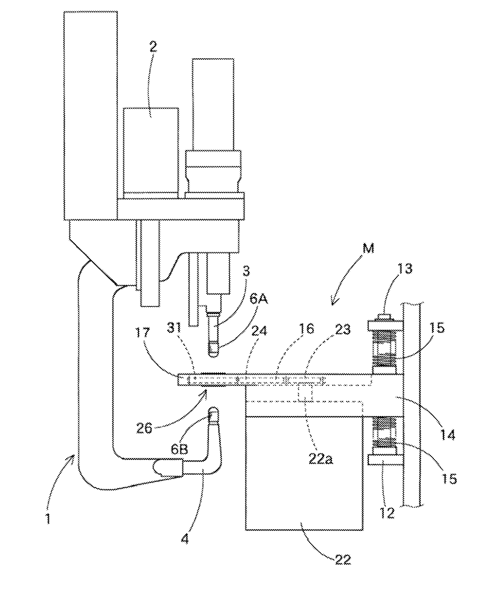
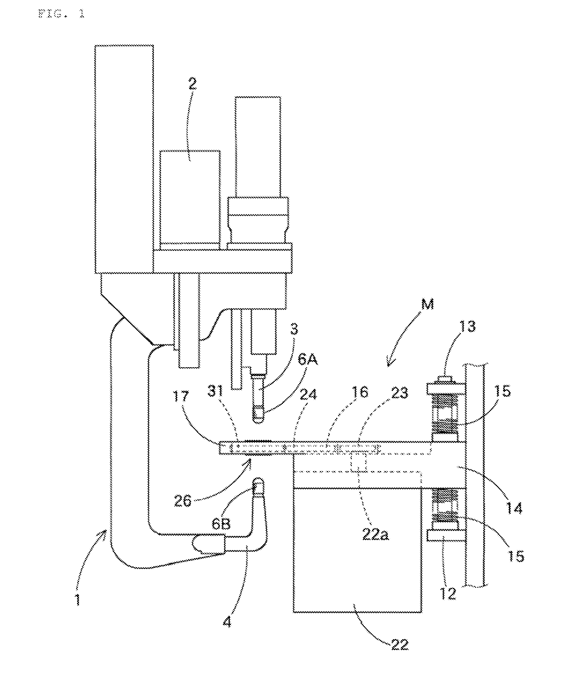
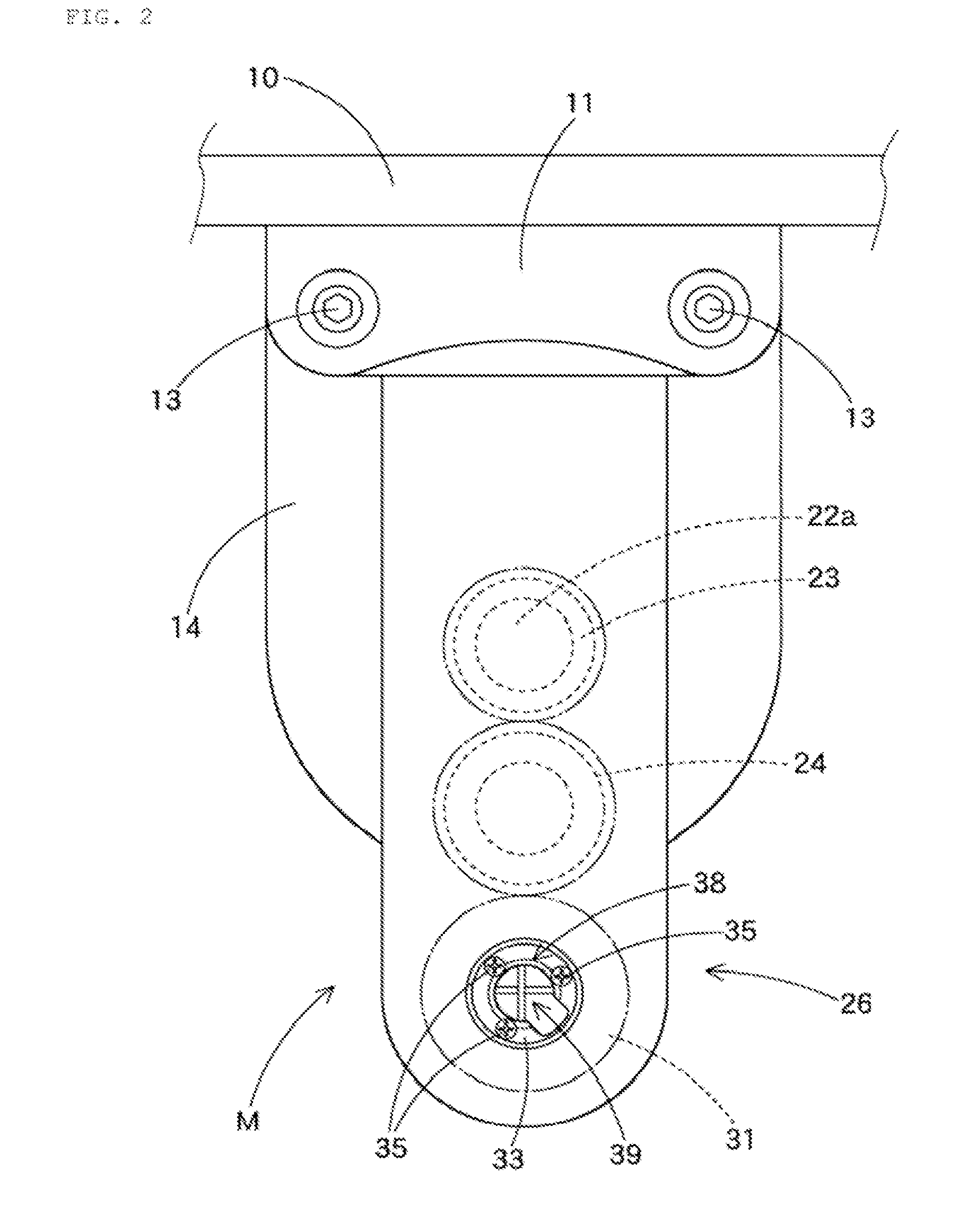
[0032]First of all, a tip dresser M according to one embodiment of the present invention, as shown in FIG. 1 and FIG. 2, grinds a par of electrode tips 6A and 6B respectively fitted into a pair of shanks 3 and 4 of a welding gun 1.

[0033]The welding gun 1 includes a servo gun retained by an end of an arm of a multi-joint welding robot (not shown in the drawings). In this case, the servo gun 1 includes a regular one that and is retained to move a pair of the electrode tips 6A and 6B by a servo motor 2 having a built-in encoder.

[0034]And, the servo gun 1 is configured to have a position control function for enabling a pair of the electrode tips 6A and 6B to approach to each other.

[0035]Moreover, the servo gun 1 is provided with a logical operation function to control a count of revolutions or the servo motor 2 and torque thereof. And, the servo gun 1 is capable of controlli...


PUM


Abstract

A tip dresser is disclosed, by which a cutter body can be easily formed and by which an end of an electrode tip can be quickly and neatly grinded. A tip dresser, which is configured to grind a pair of electrode tips used for spot welding in a manner of approaching ends of a pair of the electrode tips to each other, includes a cutter including a holder configured to foe rotationally driven with a rotation center axis matched to an axial center of each of the mutually approached electrode tips, a cutter body retained by the holder to cut vicinities of the ends of electrode tips in case the holder is rotated.

Description

CROSS-RELATED APPLICATIONS [0001]This application claims the benefit of Japanese Patent Application No. 2006-257482, filed on Sep. 20, 2006. The contents of which is hereby incorporated by reference in its entirety.BACKGROUND OF THE INVENTION[0002]1. Field of the Invention[0003]The present invention relates to a tip dresser. Although the present invention is suitable for a wide scope of applications, it is particularly suitable for grinding a pair of electrode tips used for spot welding.[0004]2. Discussion of the Related Art[0005]Generally, a cotter of a tip dresser according to a related art is configured to be stretched out in four directions from a rotation center axis. And, the tip dresser is configured to include a cutting blade provided to an edge of an end portion of a side according to each direction of the rotation center axis. So, the related art tip dresser is capable of grind each electrode tip in forward or reverse revolution (e.g., of. Japanese Patent No. 3,738,432).[0...

Claims


Application Information

Patent Timeline
IPC IPC(8): B23B5/16B23C3/12B23K11/30
CPCB23B5/166B23K11/3063Y10T29/49748Y10T409/304256Y10T29/51H03M13/1128H03M13/2975H03M13/353H03M13/6337
Inventor NAKAZIMA, KOTARO
Owner KYOKUTOH
Why Eureka
Try Eureka