Method for bonding slider row bars for photolithography process

a technology of photolithography and slider, which is applied in the direction of metal-working apparatus, record information storage, and alignment of head carriers, can solve the problems of reducing overall production efficiency, time waste, and extreme possibility of damage to slider row bars, and achieve the effect of improving the flatness of the abs-forming surfa

Inactive Publication Date: 2008-04-03
SAE MAGNETICS (HK) LTD
View PDF3 Cites 4 Cited by
  • Summary
  • Abstract
  • Description
  • Claims
  • Application Information

AI Technical Summary

Benefits of technology

[0010]One object of the invention is to provide a method for bonding a plurality of slider row bars for photolithography process, which can greatly improve flatness of ABS-forming surface of the bonded slider row bars.
[0011]Another object of the invention is to provide a method for bonding a plurality of slider row bars for photolithography process, which can reduce or avoid damage to the slider row bars during manufacturing process.
[0012]Yet another object of the invention is to provide a method for bonding a plurality of slider row bars for photolithography process, which can improve entire production efficiency.
[0013]Another object of the invention is to provide a method for manufacturing sliders, which can improve manufacturing precision of the sliders.
[0016]The step (3) may comprise: (i) attaching an auxiliary encapsulation plate having an opening to the adhesive film of the first carrier plate, such that the slider row bars are exposed from the opening; (ii) providing an encapsulation glue and dispensing it into the opening to make the encapsulation glue flow to the second surfaces of the slider row bars and gaps between the slider row bars. The encapsulation glue may be ultraviolet-curing glue. The auxiliary encapsulation plate may be made of one kind of material, such as ceramic, stainless steel, polymer or plastic, for providing sufficient structural stiffness.
[0019]As the invention utilizes the ABS forming surface of the slider row bar as the datum surface, a high overall flatness for the ABS forming surfaces is obtained during encapsulating process. Furthermore, since connection between the slider row bars and the temporary carrying tool (the first carrier plate) is eliminated by irradiation (non-immersing manner), damage to the sliders is reduced or avoided during the manufacturing process. Furthermore, as the process of bonding the slider row bars together occurs at the same time as that of bonding the slider row bars with the second carrier plate, the entire work time is decreased and the production efficiency is improved.

Problems solved by technology

However, during immersing period, as the slider row bars are also immersed into the solution, the slider row bars are extremely possible to be damaged by erosion of the solution.
In addition, in the steps 103 and 104, both curing processes of the encapsulation glue and the adhesive take a certain time respectively, and since the two steps are not performed at the same time, the encapsulation glue and the adhesive cannot be cured at the same time, thus resulting in time waste and finally lowering overall production efficiency.

Method used


Image

  • Method for bonding slider row bars for photolithography process
  • Method for bonding slider row bars for photolithography process
  • Method for bonding slider row bars for photolithography process

Examples


Embodiment Construction

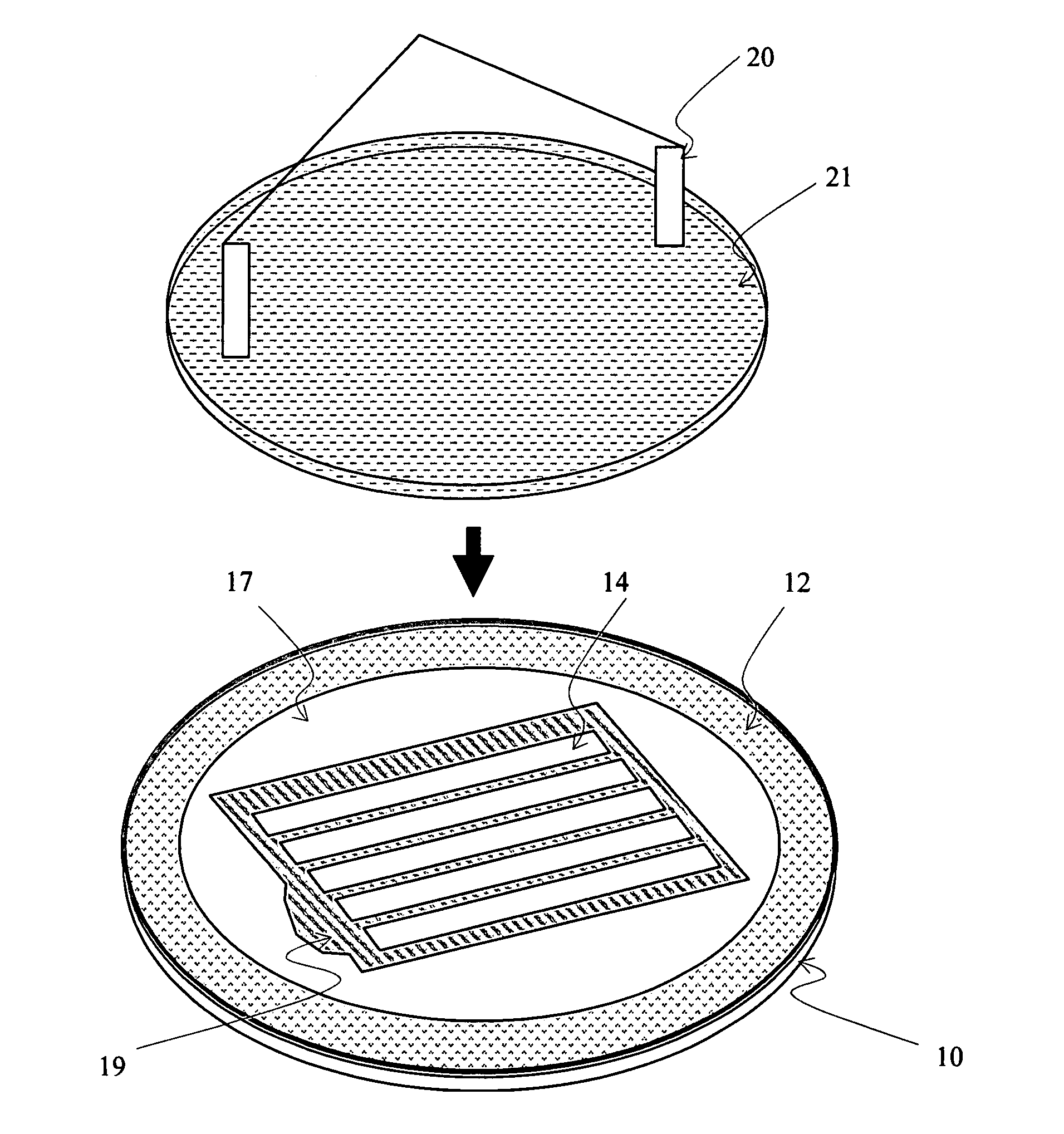
[0036]Now, according to an embodiment of the invention, a method for bonding a plurality of slider row bars together for photolithography process is described. FIG. 4 illustrates a method for bonding a plurality of slider row bars together according to an embodiment of the invention. As illustrated, the method comprises the steps of: firstly, providing a first carrier plate having a sticky surface (step 201); then, providing a plurality of slider row bars, each slider row bar having a first surface for forming ABS and a second surface opposite to the first surface, and securing each slider row bar to the first carrier plate with its first surface facing the sticky surface (step 202); next, providing an encapsulation glue and dispensing it to the second surface of each slider row bar and gaps between the slider row bars (step 203); after that, providing a second carrier plate and attaching it to the second surfaces of the slider row bars through the encapsulation glue (step 204); irr...


PUM

PropertyMeasurementUnit
perimeteraaaaaaaaaa
lift forceaaaaaaaaaa
spring forcesaaaaaaaaaa

Abstract

A method for bonding slider row bars for photolithography process, includes steps of: providing a first carrier plate having a sticky surface; providing slider row bars each having a first surface for forming ABS and an opposite second surface, and securing each slider row bar to the first carrier plate with its first surface facing the sticky surface; providing an encapsulation glue and dispensing it to the second surfaces and gaps between the slider row bars; providing a second carrier plate and attaching it to the second surfaces through the encapsulation glue; irradiating the first carrier plate and the encapsulation glue with ultraviolet light such that the first carrier plate is removed from the slider row bars, and the encapsulation glue is cured to bond the slider row bars with the second carrier plate together.

Description

FIELD OF THE INVENTION[0001]The present invention relates to a method of manufacturing sliders used in information recording disk drive units, and more particularly to a method of bonding slider row bars for photolithography process.BACKGROUND OF THE INVENTION[0002]One known type of information storage device is a disk drive device. FIG. 1a illustrates a conventional disk drive device 200 and shows a magnetic disk 101 mounted on a spindle motor 102 for spinning the disk 101. A voice coil motor arm 104 carries a head gimbal assembly (HGA) 100 that includes a slider 103 incorporating a read / write head. A voice-coil motor (VCM) is provided for controlling the motion of the motor arm 104 and, in turn, controlling the slider 103 to move from track to track across the surface of the disk 101, thereby enabling the read / write head to read data from or write data to the disk 101. In operation, a lift force is generated by the aerodynamic interaction between the slider 103 and the spinning ma...

Claims


Application Information

Patent Timeline
Patent Type & Authority Applications(United States)
IPC IPC(8): G11B5/127
CPCG11B5/102G11B5/3173G11B5/40Y10S156/922Y10S438/976Y10T29/49041Y10T29/49798Y10T29/49055Y10T156/1082Y10T29/49027Y10T156/11Y10T29/4903
Inventor LEE, TAIBOONGAO, YONGPING
Owner SAE MAGNETICS (HK) LTD
Why Eureka
Try Eureka