Substrate processing apparatus and substrate processing method

a substrate and processing apparatus technology, applied in the direction of chemistry apparatus and processes, cleaning processes and apparatus, cleaning using liquids, etc., can solve the problems of film or generating watermarks on the substrate surface, and achieve the effect of promoting liquid agitation and low surface tension

Active Publication Date: 2008-04-03
DAINIPPON SCREEN MTG CO LTD
View PDF11 Cites 52 Cited by
  • Summary
  • Abstract
  • Description
  • Claims
  • Application Information

AI Technical Summary

Benefits of technology

[0007]Incidentally, in order to replace the pure water on the substrate surface with IPA or IPA solution after rinsing processing, IPA or IPA solution needs to be fed to the respective parts of the substrate surface. Hence, when replacing processing by means of IPA or IPA solution is performed, a liquid (low surface-tension solvent) having a lower surface tension than the pure water is fed to the respective parts of the pure water adhering to the substrate surface. Then, a convective flow (Marangoni convective flow) is induced based on a surface tension difference between the pure water and the low surface-tension solvent at the respective parts of the substrate surface. This promotes the agitation of the liquid on the substrate surface, thereby increasing a chance of the liquid on the substrate surface being exposed to ambient environment (air). As a result, the dissolved oxygen concentration of the liquid (IPA or IPA solution) adhering to the substrate surface increases as replacing processing proceeds, and the substrate surface is entirely or partly oxidized, which has caused a problem of forming an oxide film or generating watermarks on the substrate surface.
[0008]An object of the present invention is to satisfactorily dry a substrate surface while preventing the generation of watermarks on the substrate surface in a substrate processing apparatus and a substrate processing method for drying the substrate surface wet with a processing liquid using a low surface-tension solvent such as IPA.
[0011]In each of these inventions, the blocking member is arranged away from the substrate surface while facing the substrate surface, and the inert gas is supplied into the clearance space defined between the blocking member and the substrate surface. The processing liquid is discharged from the processing liquid discharge port formed in the blocking member to perform the predetermined wet processing while the inert gas is supplied into the clearance space, and the low surface-tension solvent is discharged from the solvent discharge port to replace the processing liquid adhering to the substrate surface with the low surface-tension solvent while the inert gas is supplied into the clearance space. Accordingly, the wet processing with the processing liquid and the replacing processing with the low surface-tension solvent are performed while the ambient atmosphere of the substrate surface is maintained to be a low oxygen concentration atmosphere. Thus, the dissolution of oxygen into the low surface-tension solvent from the ambient atmosphere of the substrate surface can be reduced upon replacing the processing liquid adhering to the substrate surface with the low surface-tension solvent. As a result, an increase of the dissolved oxygen concentration of the low surface-tension solvent can be suppressed, and hence, it is possible to securely prevent from forming an oxide film or generating watermarks on the substrate surface. Further, since the inert gas atmosphere is set in the clearance space while the blocking member is caused to face the substrate surface, the splash of the processing liquid or the low surface-tension solvent removed from the substrate surface back to the substrate surface can be suppressed. Therefore, the adherence of particles to the substrate surface can be reduced.

Problems solved by technology

As a result, the dissolved oxygen concentration of the liquid (IPA or IPA solution) adhering to the substrate surface increases as replacing processing proceeds, and the substrate surface is entirely or partly oxidized, which has caused a problem of forming an oxide film or generating watermarks on the substrate surface.

Method used


Image

  • Substrate processing apparatus and substrate processing method
  • Substrate processing apparatus and substrate processing method
  • Substrate processing apparatus and substrate processing method

Examples


first embodiment

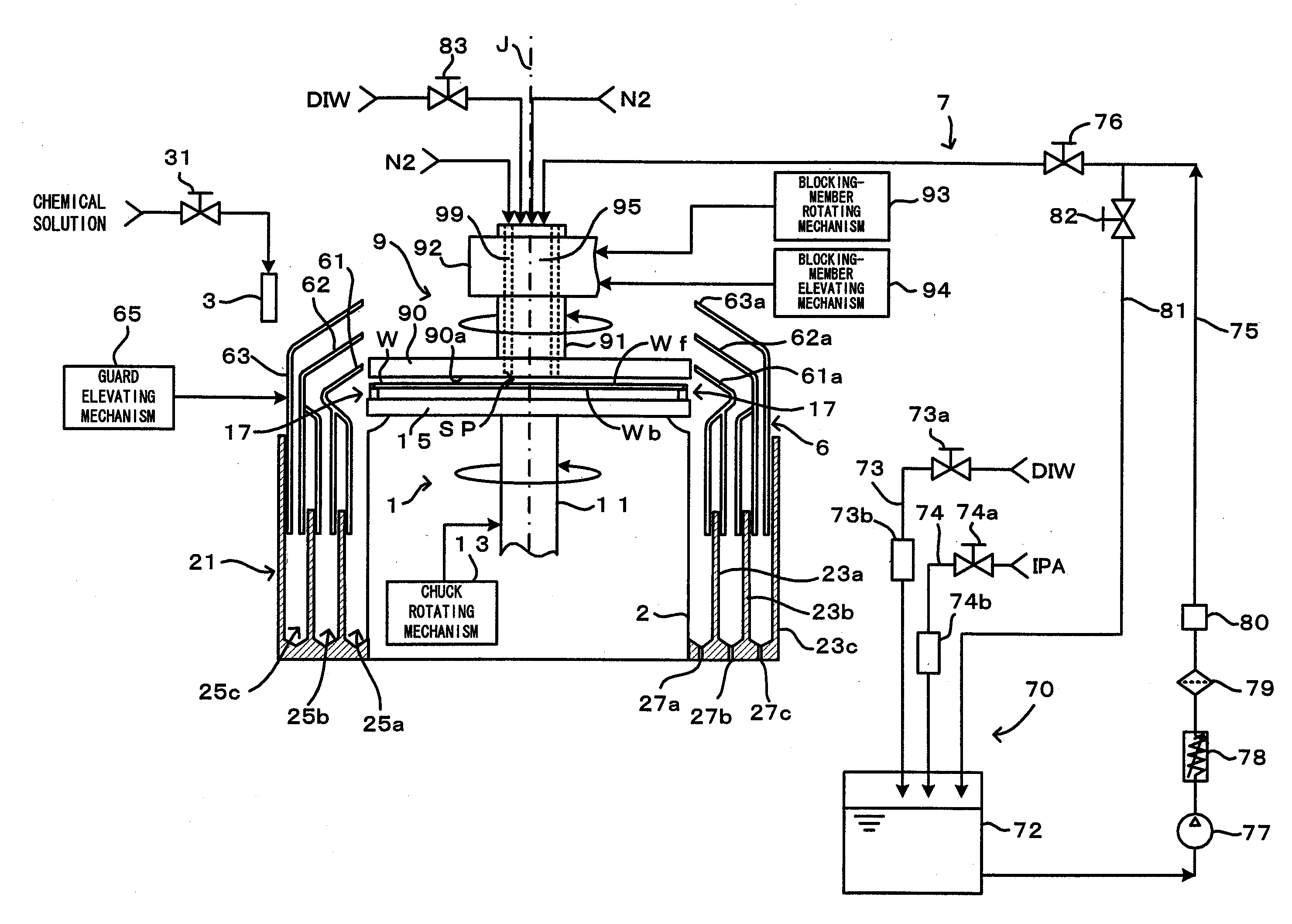
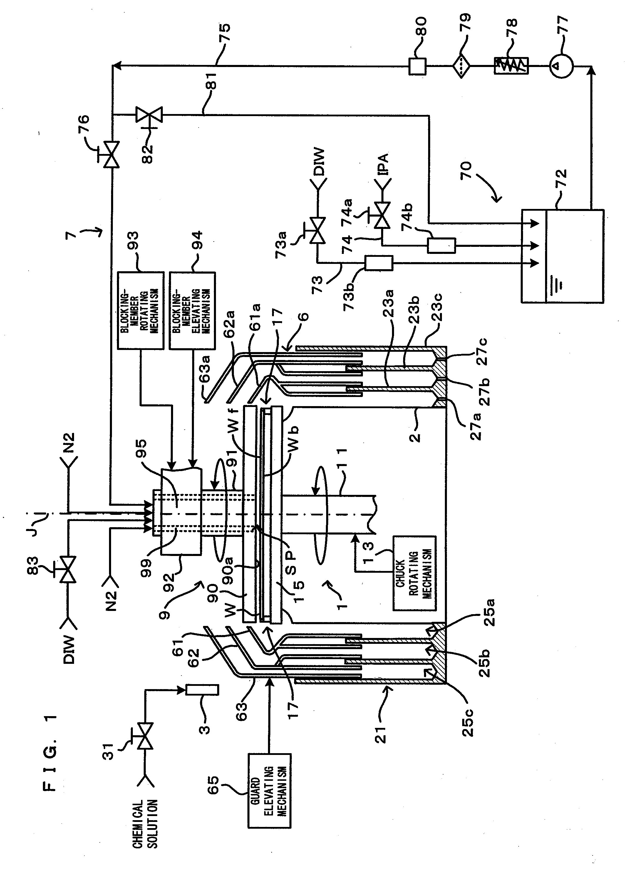
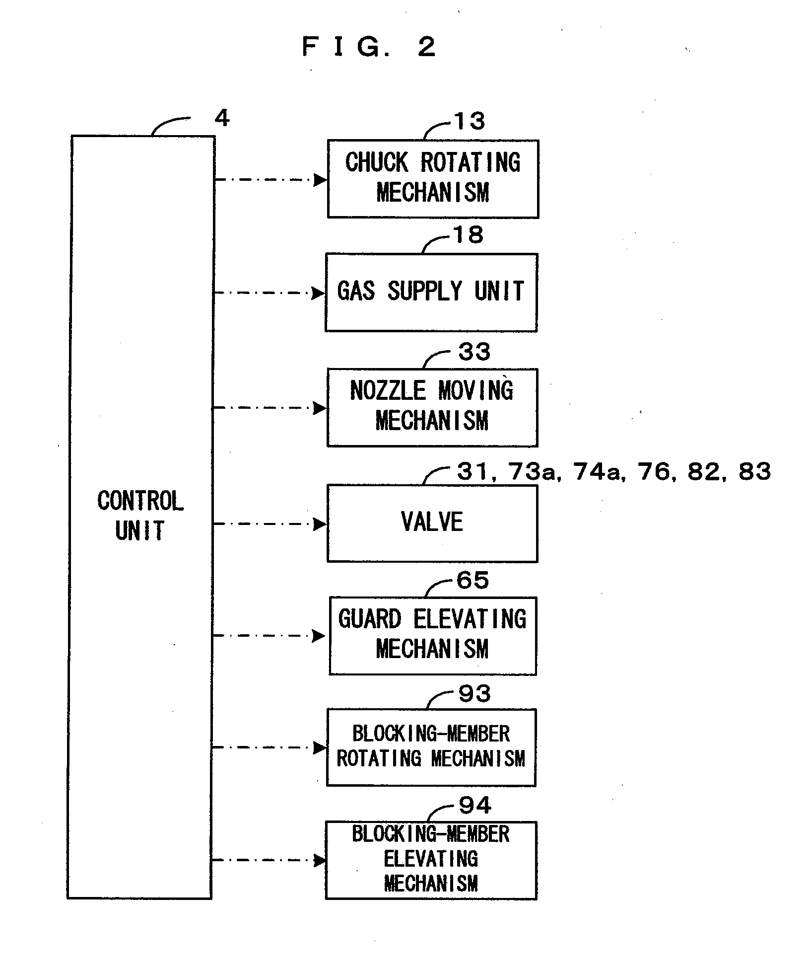
[0025]FIG. 1 is a diagram showing a first embodiment of a substrate processing apparatus according to this invention, and FIG. 2 is a block diagram showing a main control construction of the substrate processing apparatus of FIG. 1. This substrate processing apparatus is a substrate processing apparatus of a single wafer type used for cleaning processing to remove undesired substance adhering to a surface Wf of a substrate W such as a semiconductor wafer. More specifically, after applying chemical processing using a chemical solution such as a hydrofluoric acid and rinsing processing using a rinsing liquid such as pure water or DIW (deionized water) to the substrate surface Wf, this apparatus dries the substrate surface Wf wet with the rinsing liquid. In this embodiment, the substrate surface Wf means a pattern-formed surface on which a device pattern made of poly-Si or the like is formed.

[0026]This substrate processing apparatus includes a spin chuck 1, a chemical solution discharg...

second embodiment

[0075]FIG. 10 is a timing chart showing the operation of a substrate processing apparatus according to a second embodiment of the invention, and FIGS. 11A to 11C are diagrams schematically showing the operation of the substrate processing apparatus according to the second embodiment of the invention. The substrate processing apparatus according to the second embodiment largely differs from the first embodiment in that a major part of the rinsing liquid adhering to the substrate surface Wf is blown off to be removed with a part thereof left after the rinsing step and before the replacing step. The other construction and operation are not described here since being similar to those of the first embodiment.

[0076]In this embodiment, upon finishing rinsing processing, the control unit 4 sets the rotating speed of the substrate W to 300 to 500 rpm. Although a relatively large amount of the rinsing liquid (DIW) adheres to the substrate surface Wf after rinsing processing (FIG. 11A), a majo...

third embodiment

[0079]FIG. 12 is a diagram showing a third embodiment of the substrate processing apparatus according to the invention. The substrate processing apparatus according to the third embodiment largely differs from the first and second embodiments in that the plate-like member90 of the blocking member 9 is rotated as the substrate W rotates in the first and second embodiments, whereas the blocking member is arranged away from the substrate surface Wf while being held stationary without being rotated and facing the substrate surface Wf in the third embodiment. The other construction and operation are not described here since being similar to those of the first and second embodiments.

[0080]In this embodiment, a blocking member 100 is structured to move upward and downward between a facing position set in the vicinity of the surface Wf of the substrate W held by a spin chuck and a separated position sufficiently distanced upward from the substrate surface Wf, and is moved upward and downwar...


PUM


Abstract

A rinsing liquid (DIW) is discharged from a rinsing liquid discharge port formed in a blocking member to perform rinsing processing to a substrate surface while a nitrogen gas is supplied into a clearance space, and a liquid mixture (IPA+DIW) is discharged from a liquid mixture discharge port formed in the blocking member to replace the rinsing liquid adhering to the substrate surface with the liquid mixture while the nitrogen gas is supplied into the clearance space. Thus, an increase of the dissolved oxygen concentration of the liquid mixture can be suppressed upon replacing the rinsing liquid adhering to the substrate surface with the liquid mixture, which makes it possible to securely prevent from forming an oxide film or generating watermarks on the substrate surface.

Description

CROSS REFERENCE TO RELATED APPLICATION[0001]The disclosure of Japanese Patent Application No. 2006-265137 filed Sep. 28, 2006 including specification, drawings and claims is incorporated herein by reference in its entirety.BACKGROUND OF THE INVENTION[0002]1. Field of the Invention[0003]The present invention relates to a substrate processing apparatus and a substrate processing method for applying a predetermined wet processing to a substrate surface by supplying a processing liquid to the substrate surface, and then, drying the substrate surface wet with the processing liquid. Substrates to be dried include semiconductor wafers, glass substrates for photomasks, glass substrates for liquid crystal displays, glass substrates for plasma displays, substrates for FEDs (field emission displays), substrates for optical discs, substrates for magnetic discs, and substrates for magnet-optical discs.[0004]2. Description of the Related Art[0005]Numerous drying methods have already been proposed...

Claims


Application Information

Patent Timeline
Patent Type & Authority Applications(United States)
IPC IPC(8): B08B3/10B08B3/02H01L21/027H01L21/304H01L21/306
CPCH01L21/67028Y10S134/902H01L21/67051H01L21/304
Inventor MIYA, KATSUHIKOIZUMI, AKIRA
Owner DAINIPPON SCREEN MTG CO LTD
Why Eureka
Try Eureka