Technique for improved ion beam transport

a technology of ion beam and ribbon beam, which is applied in the direction of irradiation devices, electric discharge tubes, electrical apparatus, etc., can solve the problems of space charge blow-up, undesirable high energy contamination of the target substrate, and ions may lose their charge, etc., and achieve the effect of improving ion beam transpor

Active Publication Date: 2008-04-03
VARIAN SEMICON EQUIP ASSOC INC
View PDF25 Cites 25 Cited by
  • Summary
  • Abstract
  • Description
  • Claims
  • Application Information

AI Technical Summary

Benefits of technology

[0011]A technique for improved ion beam transport is disclosed. In o

Problems solved by technology

A reason for this is that transporting an ion beam at lower energy levels required at a final stage would cause space charge blow-up to occur.
A common problem with conventional ribbon beam implanters is that some ions may lose their charge in a charge exchange reaction with residual gas along a beam line.
This high energy contamination of the target substrate is undesirable and obviously may have a negative impact on a resulting implanted device.
However, a shortcoming of this solution is that a decelerated, low en

Method used


Image

  • Technique for improved ion beam transport
  • Technique for improved ion beam transport
  • Technique for improved ion beam transport

Examples


Embodiment Construction

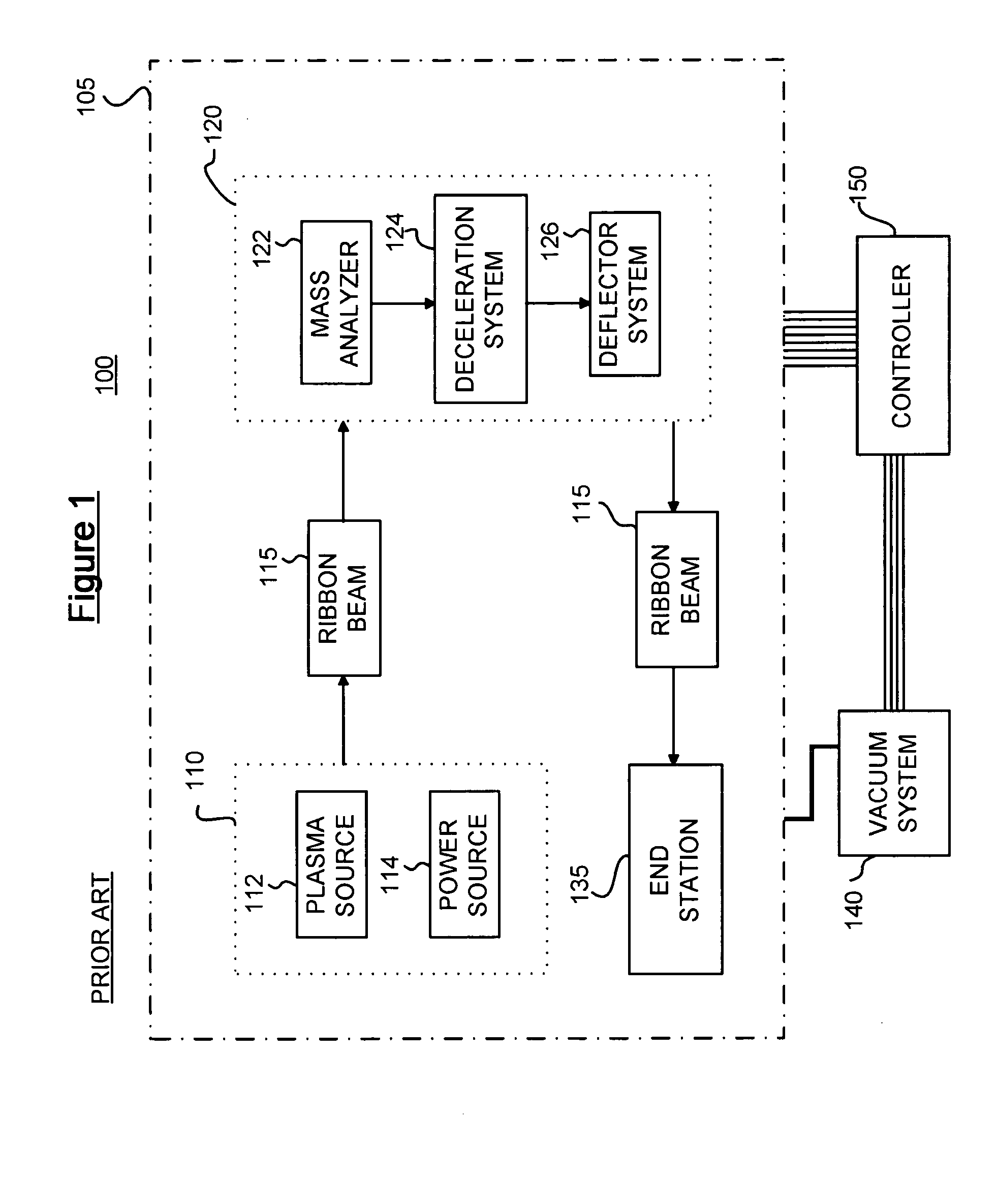
[0020]Referring now to FIG. 1, there is shown a schematic block diagram of an of an exemplary conventional ion implantation system 100 in accordance with various embodiments of the present disclosure. The system 100 includes an ion source 110 for producing a ribbon shaped ion beam 115 along a beam path. The ion source 110 includes, for example, a plasma source 112 of a particular gas with an associated power source 114. The plasma source 112 may comprise a plasma confinement chamber from which an ion beam is extracted. The extracted ion beam may comprise the ribbon shaped ion beam 115, for example, having a width of about 400 mm for implantation of a 300 mm semiconductor wafer. An exemplary ribbon beam generating ion implantation system may be found in commonly assigned U.S. Pat. No. 6,635,880, entitled “High Transmission, Low Energy Beamline Architecture For Ion Implanter,” the disclosure of which is hereby incorporated by reference in its entirety.

[0021]A beamline assembly 120 is ...


PUM


Abstract

A technique for improved ion implantation is provided. The technique is embodied as an electrostatic filter for an ion implantation device. The electrostatic filter is located just prior to deceleration and may be integrated with a decelerator. Electrodes are used to generate an electric field to separate neutrals from ions. Also, the filter may include active cooling to reduce background gas pressure, a precursor to neutral particle formation. Electrode geometry may also inhibit high energy neutrals from contaminating the target substrate.

Description

FIELD OF THE DISCLOSURE[0001]The present disclosure relates generally to substrate processing techniques and more particularly, to a technique for improved ion beam transport in a ribbon beam ion implanter.BACKGROUND OF THE DISCLOSURE[0002]In semiconductor manufacturing, ion implantation is used to change material properties of portions of a substrate. Indeed, ion implantation has become a standard technique for introducing conductivity-altering impurities into semiconductor wafers to produce various semiconductor-based products. In an ion implantation process, a desired impurity material is typically ionized in an ion source, ions are accelerated to form an ion beam of prescribed energy, and the ion beam is directed at a surface of a semiconductor wafer. Energetic ions in the ion beam penetrate into bulk semiconductor material and are embedded into a crystalline lattice of the bulk semiconductor material of the wafer to form a region of desired conductivity.[0003]Ion implantation s...

Claims


Application Information

Patent Timeline
IPC IPC(8): H01J37/317
CPCH01J37/05H01J37/3171H01J2237/04756H01J2237/028H01J2237/004H01J2237/1825H01J37/317H01L21/265
Inventor BENVENISTE, VICTOR
Owner VARIAN SEMICON EQUIP ASSOC INC
Why Eureka
Try Eureka