Low-leakage gate lines driving circuit for display device

Active Publication Date: 2008-04-03
SAMSUNG DISPLAY CO LTD
View PDF11 Cites 72 Cited by
  • Summary
  • Abstract
  • Description
  • Claims
  • Application Information

AI Technical Summary

Benefits of technology

[0011]The present disclosure of invention provides a gate-lines driving apparatus for a display

Problems solved by technology

However, even in such a case the amount of leakage current that flows through the supposedly-turned off transistor can be a significant amount for some specific applications.
Accordingly, when excess leakage current flows, it may not be possibl

Method used


Image

  • Low-leakage gate lines driving circuit for display device
  • Low-leakage gate lines driving circuit for display device
  • Low-leakage gate lines driving circuit for display device

Examples


Embodiment Construction

[0027]In the drawings, the thickness of layers, films, panels, regions, etc., may be exaggerated for clarity. Like reference numerals generally designate like elements throughout the specification. It will be understood that when an element such as a layer, film, region, or substrate is referred to as being “on” another element, it can be directly on the other element or intervening elements may also be present. In contrast, when an element is referred to as being “directly on” another element, there are no intervening elements present.

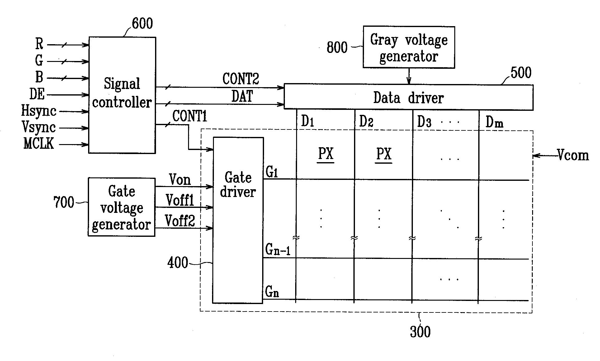
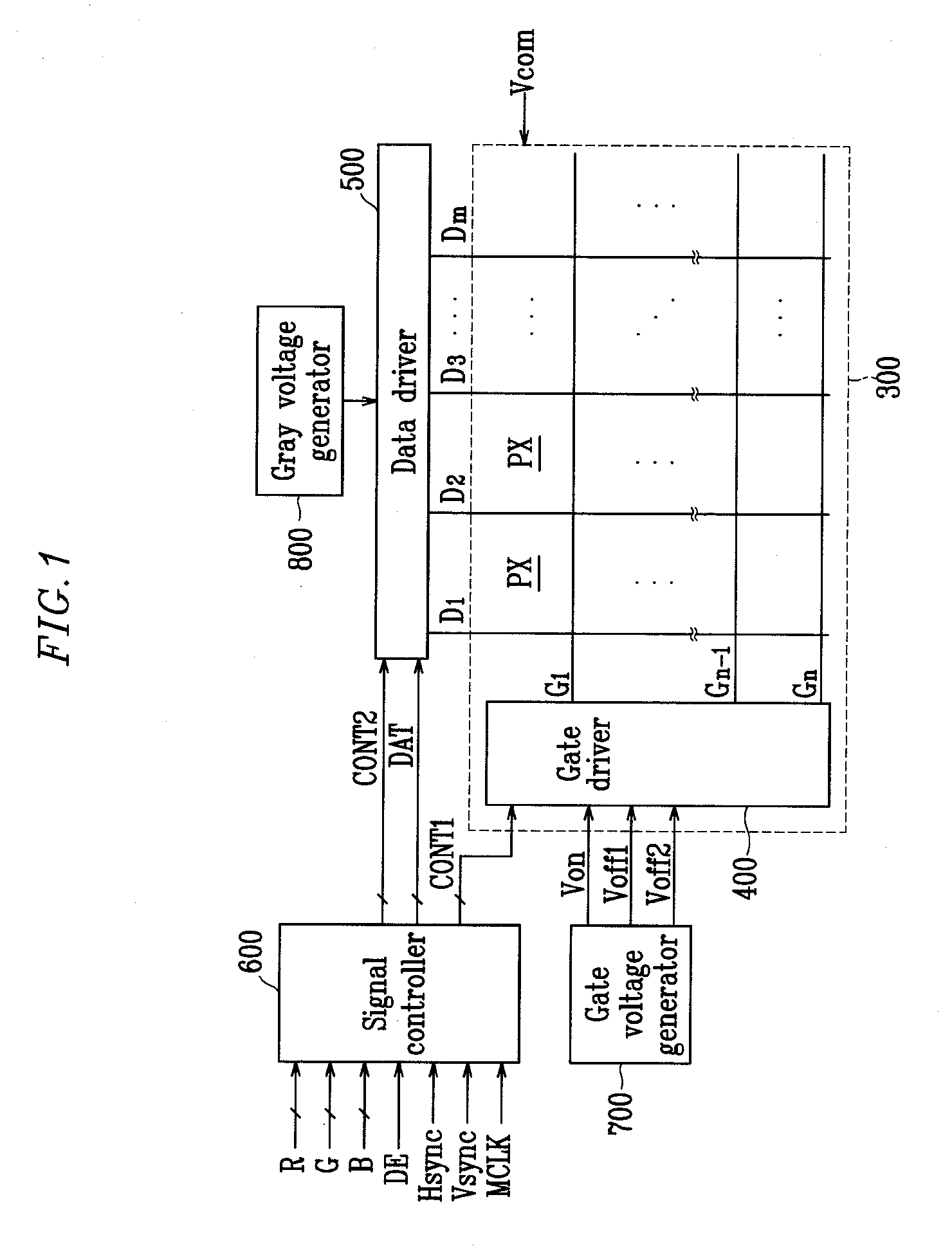
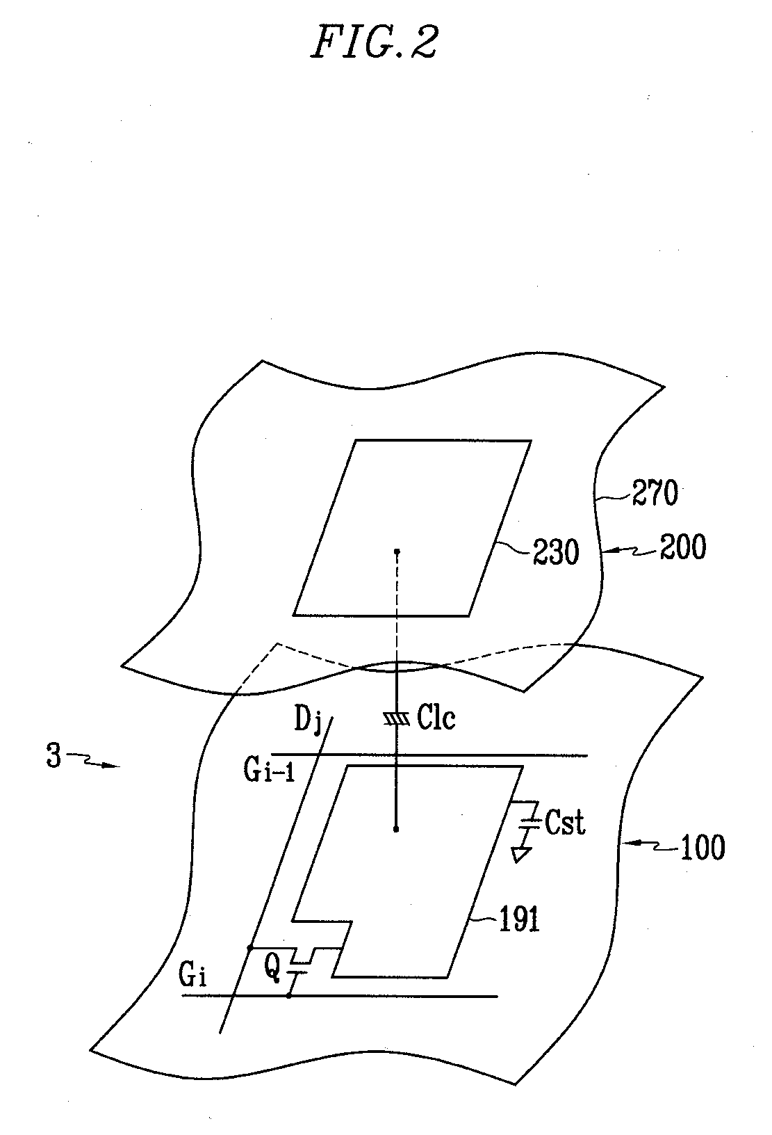
[0028]FIG. 1 is a block diagram of a liquid crystal display (LCD) including drive electronics according to the exemplary embodiment. FIG. 2 is an equivalent circuit diagram for a single pixel unit of the LCD according to the exemplary embodiment.

[0029]As shown in FIG. 1, the LCD according to the exemplary embodiment includes a liquid crystal panel assembly 300, a gate-lines driver 400 and a data-lines driver 500 that are connected to respective gate a...


PUM


Abstract

A gates-line driving circuit of a display device includes a plurality of stages that are serially connected to each other, where each stage includes a plurality of transistors and a plurality of capacitors and receives a scanning start signal, a plurality of clock signals, and first and second gate-off voltages Voff1 and Voff2 of different magnitudes, where some of the transistors are turned off with the first gate-off voltage, and others of the transistors are turned off with the second gate-off voltage.

Description

CROSS-REFERENCE TO RELATED APPLICATION[0001]This application claims priority to and benefit of Korean Patent Application No. 10-2006-0095981 filed in the Korean Intellectual Property Office on Sep. 29, 2006, the entire disclosure of which is incorporated herein by reference.BACKGROUND[0002](a) Field of Invention[0003]The present disclosure of invention relates to driving circuitry of a display device.[0004](b) Description of Related Art[0005]In recent years, as a substitute for heavy and large cathode ray tubes (CRTs), flat panel displays, such as organic light emitting diode (OLED) displays, plasma display panels (PDPs), and liquid crystal displays (LCDs) have been actively developed.[0006]The PDP is a device that can display characters and / or images by using a light-emitting plasma that is generated according to selective activation of a gas discharge. The OLED displays characters and / or images by using selective activation of field emission effects of particular organic materials...

Claims


Application Information

Patent Timeline
IPC IPC(8): G09G5/00
CPCG09G3/3677G11C19/184G09G2320/02G09G3/20G09G3/30G09G3/36G11C19/00
Inventor SHIN, SEOBKIM, YEONG-KOO
Owner SAMSUNG DISPLAY CO LTD
Why Eureka
Try Eureka