Circuit Module

Active Publication Date: 2008-04-03
AUTONETWORKS TECH LTD +2
View PDF10 Cites 41 Cited by
  • Summary
  • Abstract
  • Description
  • Claims
  • Application Information

AI Technical Summary

Benefits of technology

[0005]In the above circuit module, there is a need for electrical direct connection between a specific bus bar and the control circuit built in the control circuit board, in some cases. As measures for this need, the above Patent Publication 1 discloses a method for interconnection between the specific bus bar and the control circuit board by providing the control circuit board with a th

Problems solved by technology

This disadvantage becomes prominent as a diameter of the t

Method used


Image

  • Circuit Module
  • Circuit Module
  • Circuit Module

Examples


Embodiment Construction

[0020]A preferred embodiment of the present invention will be described based on the drawings. The basic constitution of a circuit module and a production process therefor according to this embodiment are equivalent to those disclosed in the aforementioned Patent Publication 1. Thus, the basic configuration will be described only about an outline thereof.

[0021]Firstly, there is described one example of a production process for a circuit module. However, a circuit module according to the present invention is not limited to a product produced by the following process.

[0022](1) Bus Bar Forming Process

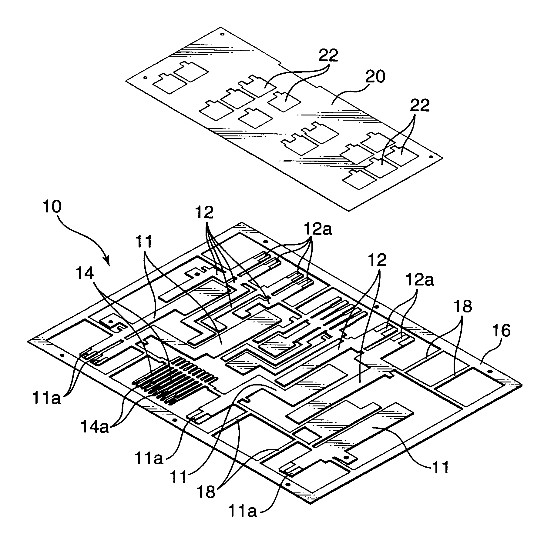
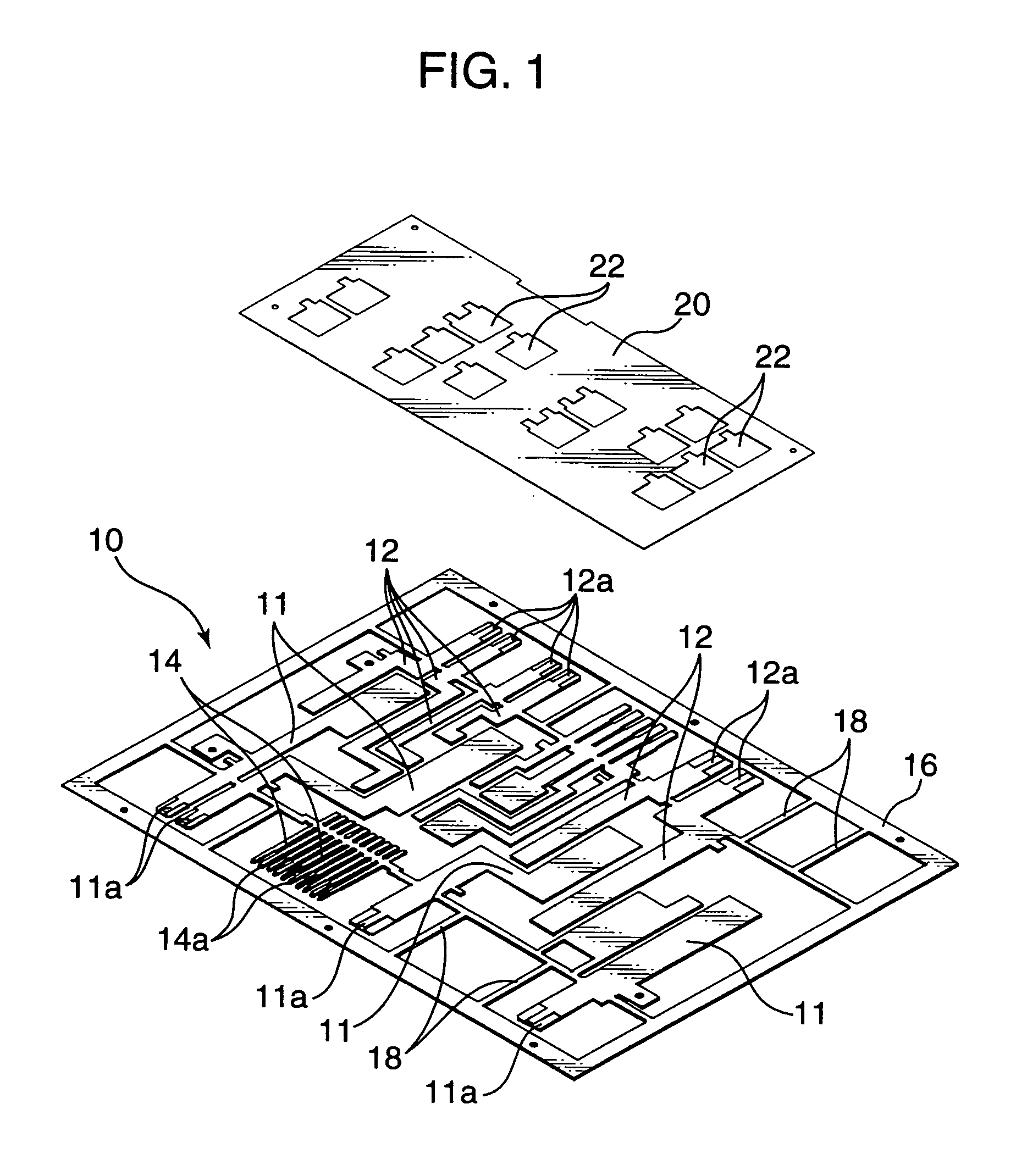
[0023]For producing the circuit module, there is formed a bus bar plate element 10 as shown in FIG. 1.

[0024]The illustrated bus bar plate element 10 comprises a rectangular-shaped outer frame 16, inside which a large number of bus bars including a plurality of input-terminal bus bars 11 each adapted to form an input terminal, a plurality of output-terminal bus bars 12 each adapted to form ...


PUM


Abstract

In respect to an electrical connection between a control circuit board 20 and bus bars 14 interbonded together, it is an object to enhance stability in quality and reliability in connection. As a solution for achieving the object, the control circuit board 20 is provided with a conductor segment 26 to be electrically connected to a specific one of the bus bars 14 on the opposite side of a rear surface thereof bonded to the bus bars 14, and a through-hole 24 penetrating a main body thereof at a position adjacent to the conductor segment 26 so as to expose the specific bus bar 14 therethrough. Further, an electrically-connecting member 70 is disposed to bridge over the through-hole 24 and the conductor segment 26, and soldered onto the conductor segment 26 and the bus bar portion located in the through-hole 24.

Description

TECHNICAL FIELD[0001]The present invention relates to a circuit module having a combination of a plurality of bus bars to form a power circuit to be mounted on an automobile or the like, and a control circuit board in which a control circuit for the power circuit is built.BACKGROUND ART[0002]Heretofore, as means for distributing electric power from a common vehicle-mounted power supply to respective electronic units, there has been widely known an electric junction box comprising a power distribution circuit formed by laminating a plurality of bus bar boards, and a circuit control element, such as a fuse and a relay switch, inserted in the power distribution circuit.[0003]Late years, with a view to downsizing the distribution circuit unit, a circuit module as disclosed in the following Patent Publication 1 has been developed. This circuit module is designed such that a plurality of bus bars forming a power circuit are arranged approximately in the same plane and bonded on one of opp...

Claims


Application Information

Patent Timeline
IPC IPC(8): H05K1/18H01R11/01H02G3/16H05K1/02H05K1/14H05K3/20H05K3/34H05K3/40H05K7/06
CPCH05K1/0263H05K1/141H05K3/202H05K3/341H05K3/3447H05K2201/10363H05K2201/0394H05K2201/10272H05K2201/1028H05K2201/10295H05K3/4046
Inventor SHIMIZU, TOSHIKITAKAGI, KOUICHIMIZUNO, FUMIAKI
Owner AUTONETWORKS TECH LTD
Why Eureka
Try Eureka