Method and system for integrated dwdm transmitters

Active Publication Date: 2008-04-03
FUTUREWEI TECH INC
View PDF54 Cites 20 Cited by
  • Summary
  • Abstract
  • Description
  • Claims
  • Application Information

AI Technical Summary

Benefits of technology

[0006]The present invention is directed to fiber optical transport systems. More particularly, the invention provides a method and system for reducing the size and cost of optical transport

Problems solved by technology

Even though these conventional DWDM systems are useful in some areas, they ha

Method used


Image

  • Method and system for integrated dwdm transmitters
  • Method and system for integrated dwdm transmitters
  • Method and system for integrated dwdm transmitters

Examples


Embodiment Construction

[0026]The present invention is directed to fiber optical transport systems. More particularly, the invention provides a method and device for reducing the size and cost of optical transmitter systems. Merely by way of example, the invention has been applied to DWDM optical transport systems. But it would be recognized that the invention has a much broader range of applicability.

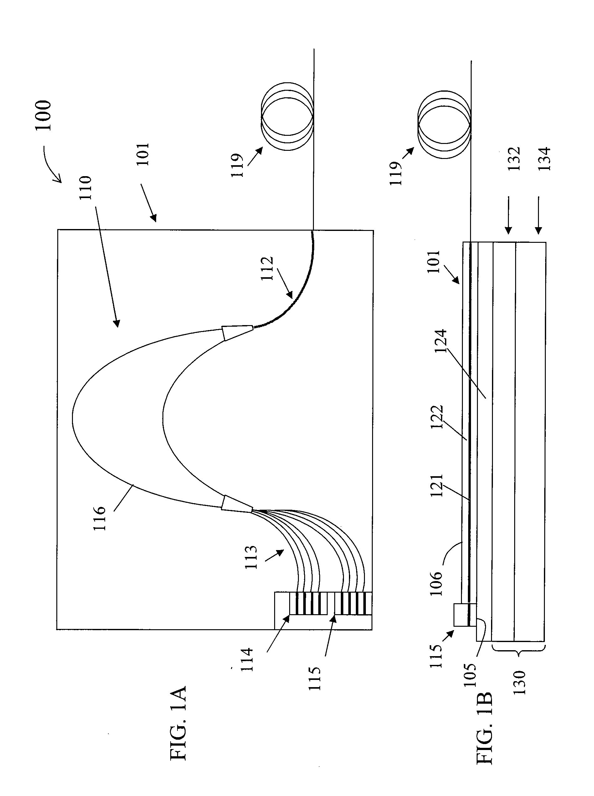
[0027]As discussed above, the optical components in a conventional DWDM system are usually individually packaged. To a great extent, the packaging cost determines the price of the components. For example, a bare distributed feedback (DFB) laser chip may cost only a few dollars, while a packaged DFB laser sells for several hundred dollars, mostly due to the cost of packaging. It is thus difficult to further reduce the cost with the conventional DWDM system design. In addition, the multiple linecards, each built with the individual components, make it difficult to reduce the size of the DWDM terminals.

[0028]In ...


PUM


Abstract

An integrated DWDM transmitter apparatus includes a support component and a silica-on-silicon substrate overlying the support component. The support component includes a temperature adjustment component. The silica-on-silicon substrate overlies the support component and includes a silica layer and a silicon layer. The silica-on-silicon substrate includes a corresponding a substrate surface which includes a first surface region and a second surface region. In an embodiment, the two surface regions are not coplanar. The transmitter apparatus includes an optical multiplexer within the silica layer, the optical multiplexer including a plurality of input waveguides and at least an output waveguide. The transmitter apparatus also includes one or more semiconductor laser array chips overlying the first surface region of the silica-on-silicon substrate. Each of the laser array chips including two or more lasers, which are optically coupled to corresponding ones of the plurality of input waveguides.

Description

CROSS-REFERENCES TO RELATED APPLICATIONS[0001]This application is a continuation-in-part of U.S. patent application Ser. No. 11 / 696,472, filed Apr. 4, 2007, which claims priority to U.S. Provisional Patent Application No. 60 / 827,825, filed Oct. 2, 2006, both commonly assigned. Additionally, this application claims priority to U.S. Provisional Patent Application No. 60 / 827,825, filed Oct. 2, 2006. Both U.S. patent application Ser. No. 11 / 696,472 and U.S. Provisional Patent Application No. 60 / 827,825 are incorporated herein by reference for all purposes.[0002]Moreover, this application is related to co-pending U.S. patent application Ser. No. 11 / 829,295, filed Jul. 27, 2007, commonly assigned, incorporated by reference herein for all purposes.BACKGROUND OF THE INVENTION[0003]The present invention is directed to fiber optical transport systems. More particularly, the invention provides a method and system for reducing the size and cost of optical transmitter systems. Merely by way of e...

Claims


Application Information

Patent Timeline
IPC IPC(8): H04J14/02
CPCH01S5/026H04J14/02H04B10/506H01S5/0268
Inventor BAI, YU SHENG
Owner FUTUREWEI TECH INC
Why Eureka
Try Eureka