Stent for Endovascular Procedures

Inactive Publication Date: 2008-04-03
VASCULAR INNOVATIONS
View PDF99 Cites 161 Cited by
  • Summary
  • Abstract
  • Description
  • Claims
  • Application Information

AI Technical Summary

Benefits of technology

[0013] In another example, a stent graft for deployment within a body vessel is provided. The stent graft includes a tubular graft and a support stent, at least a portion of which lies within the tubular graft. The graft has a proximal end and a distal end. The support stent has a proximal end and a distal end, and comprises at least one wire forming a first helical wire portion having a first translational direction about an axis of the support stent and a second helical wire portion having a second translational direction about the axis opposite the first translational direction. When the support stent is in a compressed delivery configuration, the support stent has a first diameter and a first length, and when the support stent is in an expanded deployed configuration, the support stent has a second diameter

Problems solved by technology

With many conventional catheters, implant movement during deployment may occur from frictional interference or contact with the catheter sheath as the catheter sheath is retracted from about the implant.
Moreover, covering undesired locations, such as healthy vessels and/or branch vessels, due to inaccurate implant placement may cause unfavorable clinical consequences, such as branch vessel occlusion and/or restenosis.
Such migration may result in inaccurate positioning of the stent graft with respect to the lesion site.
Further, in abdominal aneurysm procedures, an inadequate distance between an edge of the renal artery and an edge of the aneurysm, commonly referred to as a “short neck,” may prevent or limit a patient's acceptance of an endovascular treatment or procedure.
Such element overlap in these stent grafts may

Method used


Image

  • Stent for Endovascular Procedures
  • Stent for Endovascular Procedures
  • Stent for Endovascular Procedures

Examples


Embodiment Construction

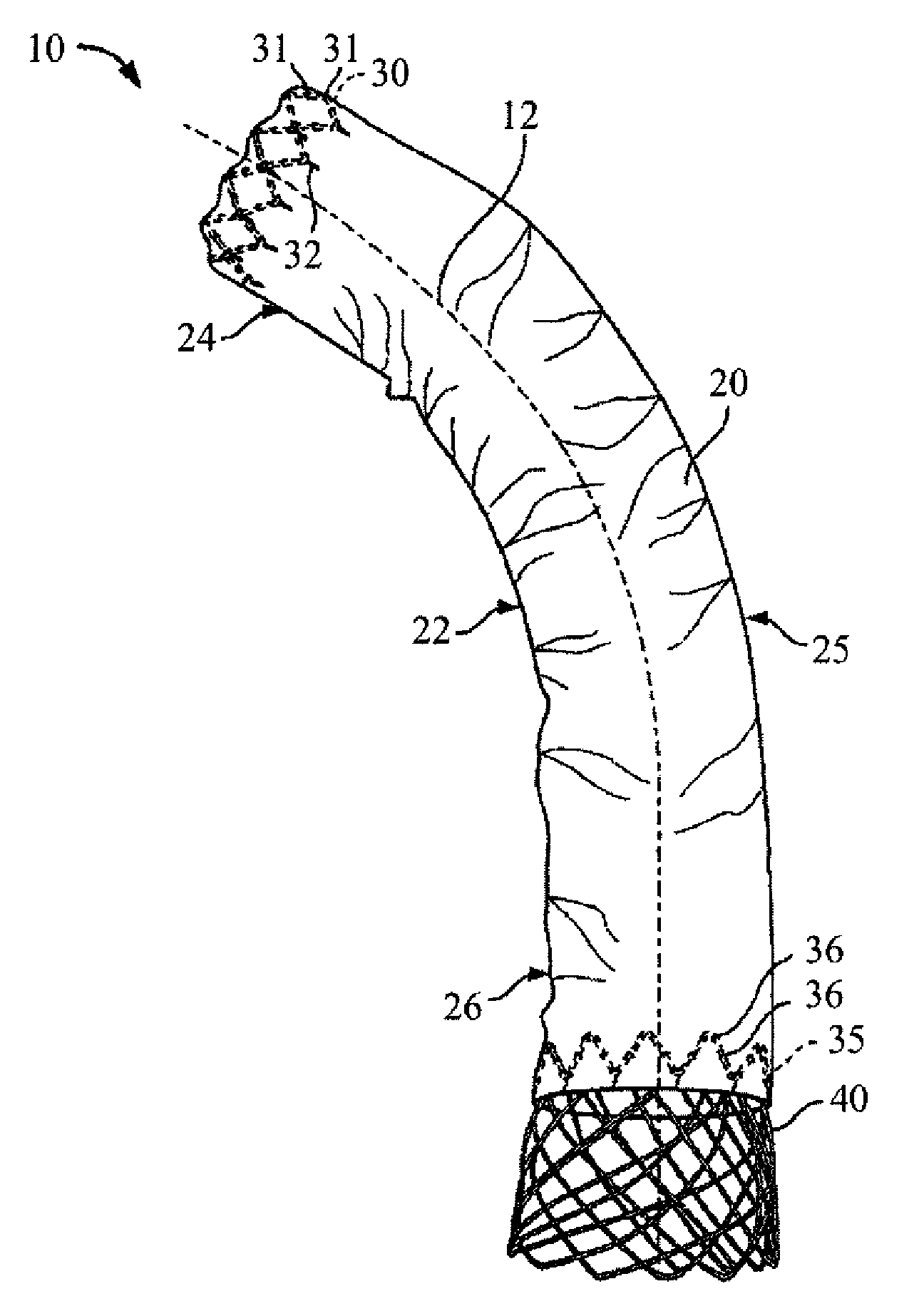
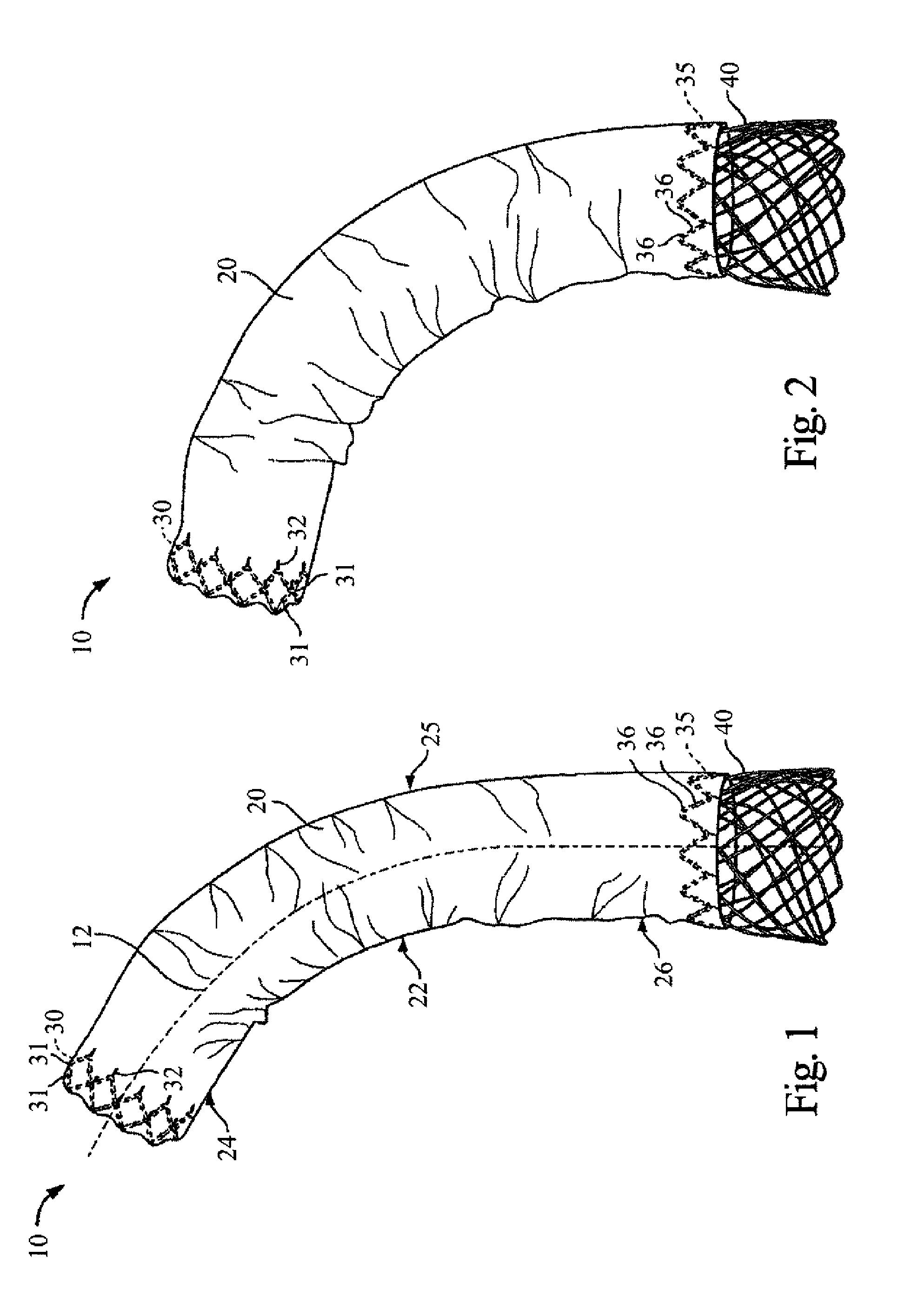
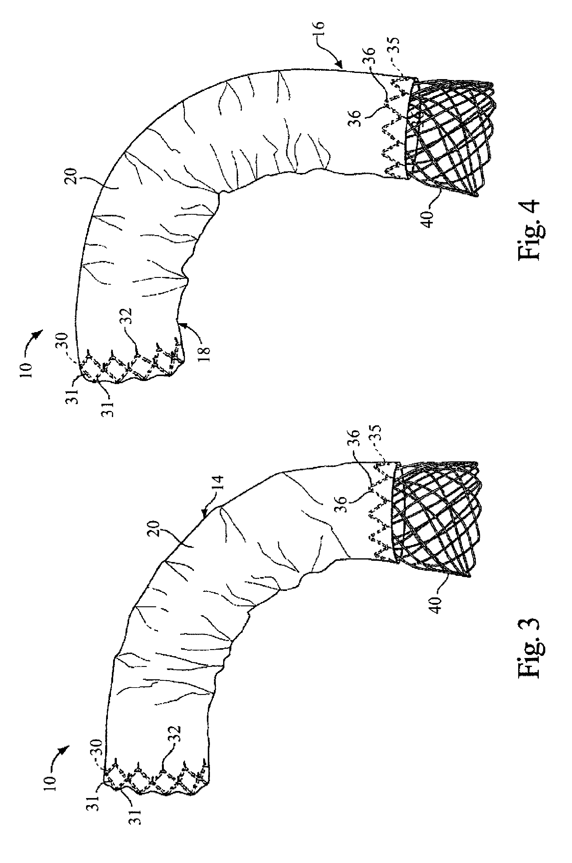
[0132] The present invention provides a stent and stent graft, for example for repairing and / or treating aneurysms, such as abdominal aortic and thoracic aortic aneurysms. The stent and stent graft may have a configuration that, upon deployment, adapts or conforms to the body vessel. More specifically, with the stent or stent graft positioned at a lesion site within a curved portion of a blood vessel, the stent or stent graft is adaptable to the anatomical curvature of the blood vessel.

[0133] The present invention is described below in reference to its application in connection with endovascular treatment of thoracic aortic aneurysms and dissections. However, it is likewise applicable to any suitable endovascular treatment or procedure including, without limitation, endovascular treatment of abdominal aortic aneurysms and dissections.

[0134] Unless otherwise defined, all technical and scientific terms used herein have the same meaning as commonly understood by one of ordinary skill...


PUM


Abstract

A stent graft for deploying a stent graft at a lesion site is provided. The stent graft comprises a tubular graft and a support stent, at least a portion of which lies within the tubular graft. The graft has a proximal end and a distal end. The support stent has a proximal end and a distal end, and comprises at least one wire forming a first helical wire portion having a first translational direction about an axis of the support stent and a second helical wire portion having a second translational direction about the axis opposite the first translational direction. When the support stent is in a compressed delivery configuration, the support stent has a first length, and when the support stent is in an expanded deployed configuration, the support stent has a second length which is less than the first length. When in the delivery configuration, the support stent is attached to the graft only at or near the proximal end of the graft.

Description

RELATED APPLICATIONS [0001] This application claims the benefit of: 1) provisional U.S. Patent Application Ser. No. 60 / 848,197, filed Sep. 28, 2006; 2) provisional U.S. Patent Application Ser. No. 60 / 848,198, filed Sep. 28, 2006; 3) provisional U.S. Patent Application Ser. No. 60 / 848,232, filed Sep. 28, 2006; and 4) provisional U.S. Patent Application Ser. No. 60 / 848,246, filed Sep. 28, 2006, all of which are incorporated herein by reference in their entirety.BACKGROUND OF THE INVENTION [0002] Expandable endovascular prosthetic implants, such as stents and stent grafts, can be loaded into a catheter for delivery and deployment at a lesion site, such as an aneurysm or dissection within a patient's vascular system. The catheter is typically configured to retain the prosthetic implant in a delivery configuration during delivery to the lesion site. At the lesion site, the prosthetic implant may be deployed, for example by retracting a catheter sheath from the prosthetic implant's proxim...

Claims


Application Information

Patent Timeline
IPC IPC(8): A61F2/06A61F2/90
CPCA61F2/07A61F2/90A61F2/95A61F2/89A61F2002/9511A61F2002/9517A61F2002/9665A61F2002/075A61F2/9517
Inventor TSENG, DAVID YILLORT, FRANCISCO MOISES
Owner VASCULAR INNOVATIONS
Why Eureka
Try Eureka