Method of in-line purification of CVD reactive precursor materials

a technology of reactive precursor materials and in-line purification, which is applied in the direction of dispersed particle separation, separation processes, coatings, etc., can solve the problems of limited film property control, loss of device yield, and relatively complicated design of the vapor-liquid separator described above, and achieves the effect of easy integration

Active Publication Date: 2008-04-10
SPTS TECH LTD
View PDF19 Cites 7 Cited by
  • Summary
  • Abstract
  • Description
  • Claims
  • Application Information

AI Technical Summary

Benefits of technology

[0016] We have devised an apparatus useful for and a method of removing impurities from liquid precursor materials used to generate reactive precursor vapors from which thin films and layers are formed on a substrate. The apparatus is easily integrated into the apparatus used in the layer deposition process. The method is particularly useful when the deposition process provides for precise addition of quantities of different combinations of reactants during a single step or when there are a number of different individual steps in the layer formation process, where the presence of impurities has a significant effect on both the quantity of reactant being charged and the overall composition of the reactant from which the layer is generated.

Problems solved by technology

Historically, these types of layers were deposited from a liquid phase, resulting in limited film property control and loss of device yield due to capillary forces.
The design of the vapor-liquid separators described above is relatively complicated, which is due at least in part to the need to have a continuous flow of liquid to a downstream process.
As a result, when a given amount of reactive vapor is charged to a processing chamber in which the coating is formed on a substrate, due to the impurity content of the vapor, there may not be sufficient reactant to produce full coverage of the substrate surface by the deposited layer.
Further, the impurities may affect the chemical composition and physical properties of the deposited layer.
This increases the problem of the presence of impurities in the precursors, which impurities become part of the vapor produced from the precursors.

Method used


Image

  • Method of in-line purification of CVD reactive precursor materials
  • Method of in-line purification of CVD reactive precursor materials
  • Method of in-line purification of CVD reactive precursor materials

Examples


example one

Removal of Protective Gases from Precursor Composition Supply

[0064] Freshly filled supply cylinders provided by vendors, which act as the precursor composition supply vessel, are frequently pressured with an inert gas such as nitrogen at atmospheric pressure to provide a “blanket” over the precursor composition, which prevents the entry of contaminants from ambient. When a blanketing gas is used to protect the precursor composition, the precursor purification process can be used to remove the blanketing gas. When the precursor composition supply vessel is one which is emptied and refilled, gaseous impurities present in tank trucks or from rail tankers may require similar removal of protective gases.

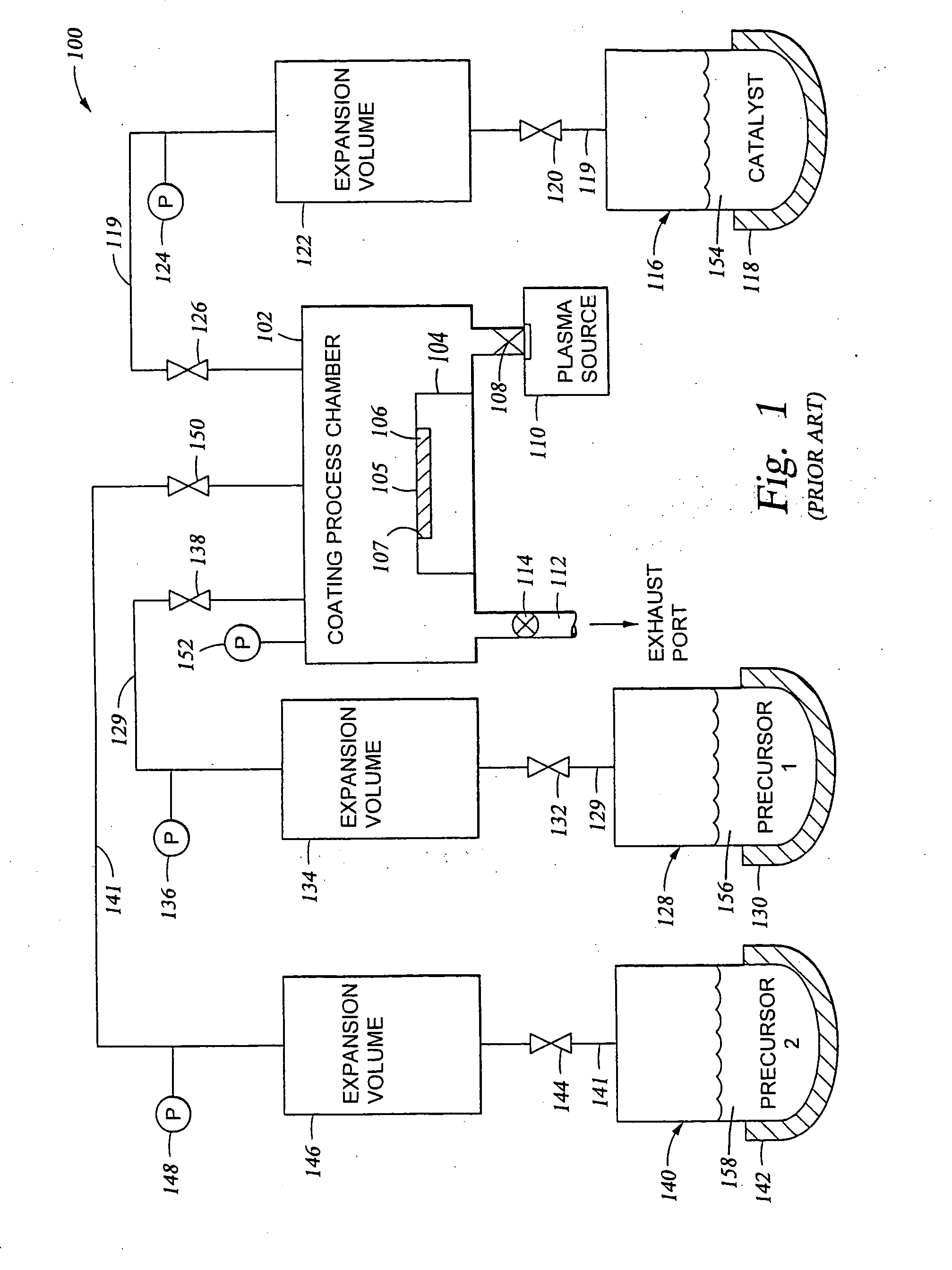
[0065] The procedure for protective gas removal is as follows, with reference to FIG. 2B:

[0066] 1) With shut off valve 204 closed, and downstream optional bypass valve 212 (if present) and line valve 214 closed, the fluid flow conduits between the shut off valve 204 and the vacuum (pre...

example two

Removal of Impurities from a Precursor Composition at Room Temperature

[0079] After the protective gases, or air, or other vapors have been removed to the extent that the pressure sensor maximum is not exceeded by the gaseous materials exiting the liquid precursor composition supply vessel, it is possible to proceed with the removal of other impurities present in the liquid precursor composition.

[0080] Subsequent to the steps shown in Paragraph [0065} above, impurity removal with the precursor composition at room temperature is as follows, with reference to FIG. 2B:

[0081] 1) With shut off valve 204 open 100% and variable aperture valve 206 opened 100%, restrictor valve 208 is opened for a time period ranging from about 5 seconds to about 60 seconds (typically 30 seconds is adequate) to release a portion of the volatile gases from the precursor composition supply vessel 202 through the conduits 203 and 205 into the limited volume chamber 210. (Exhaust valve 212 (if present) and lin...

example three

Removal of Impurities from a Precursor Composition at Elevated Temperature

[0086] The method of the invention is typically used to remove additional impurities from the precursor composition up to about the temperature at which the reactive precursor is to be used during deposition of a thin film / layer. This reduces the effect on the deposited layer of remaining impurities which are present in the reactive precursor during deposition of the layer.

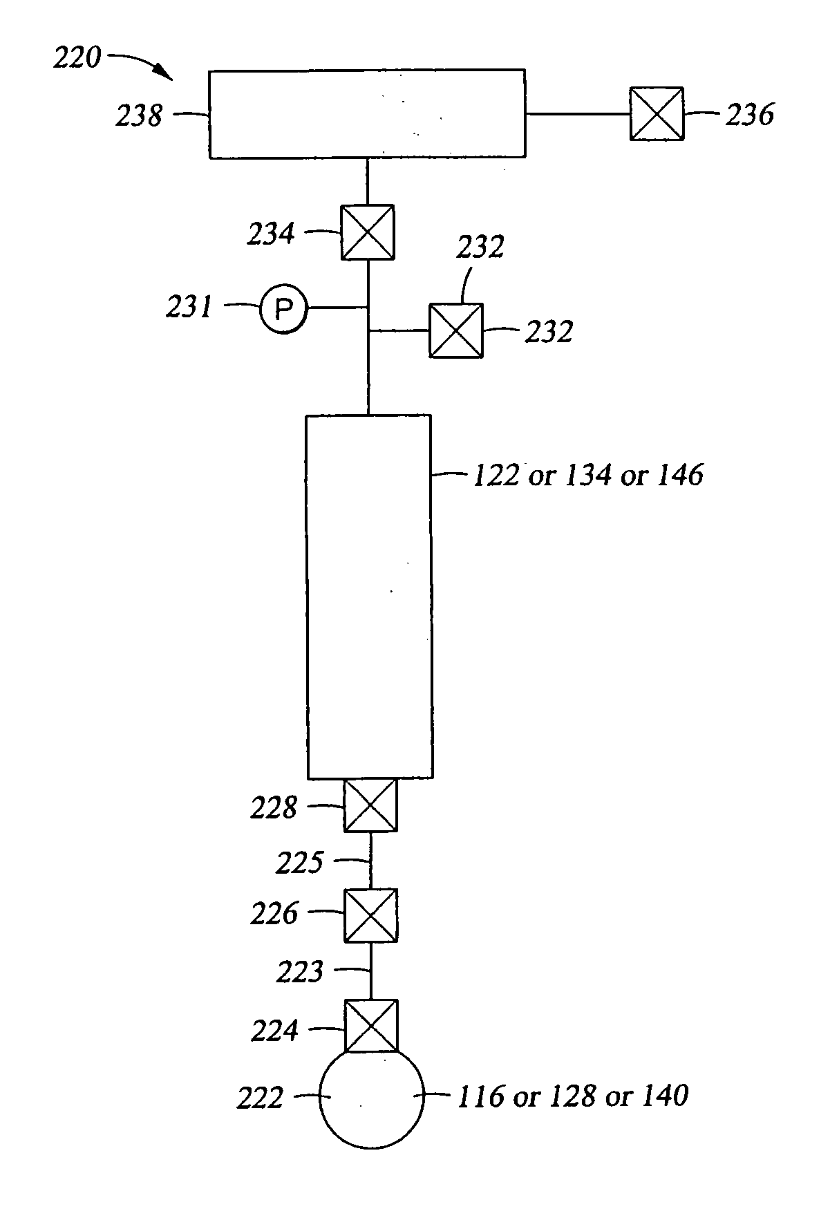
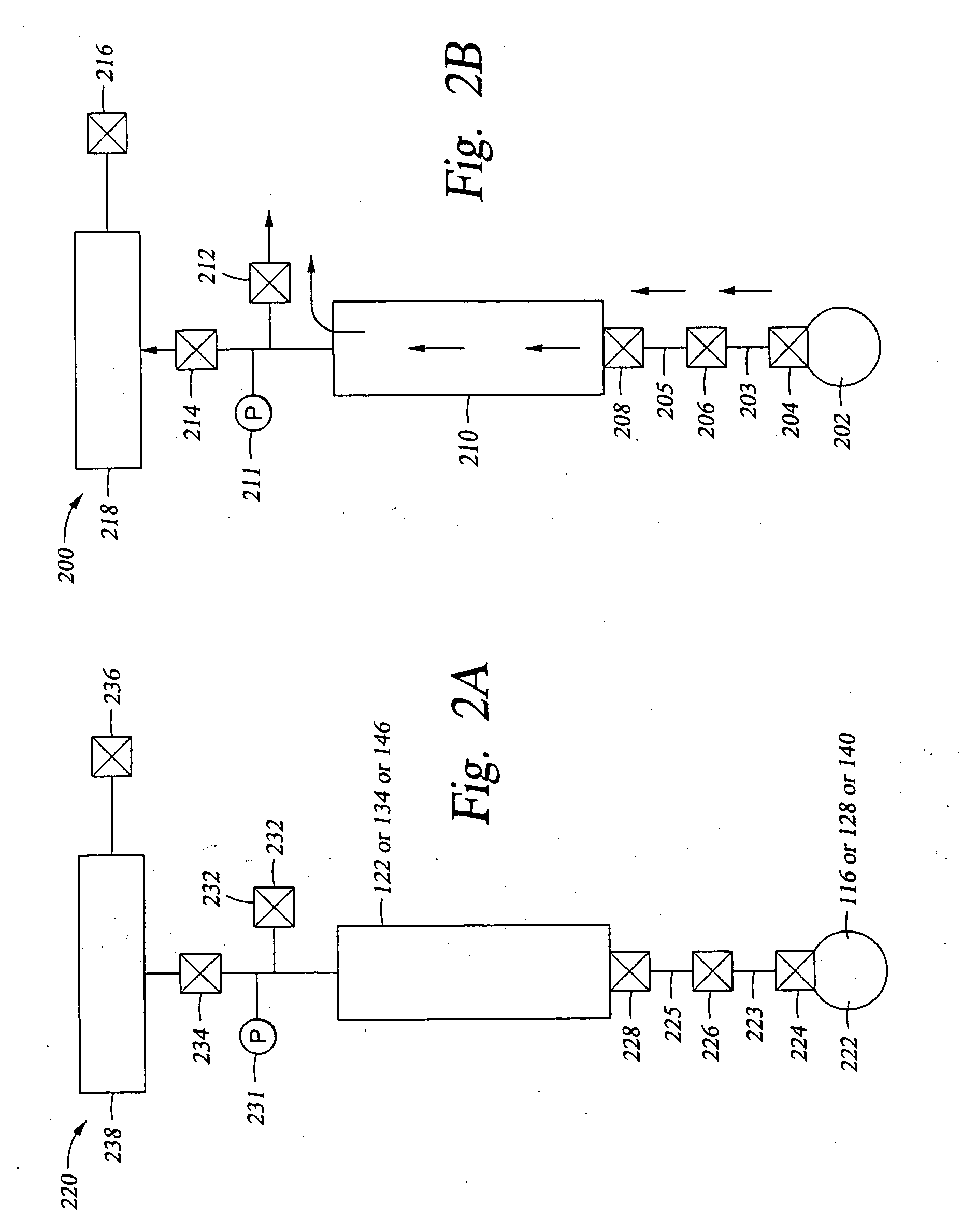
[0087] One skilled in the art, will be able to determine the boiling point of a given liquid reactant precursor at a given subatmospheric pressure which is present in the limited volume container (typically the expansion volume, 122, 134, or 146) by using a combination of tools such as those shown in FIGS. 3A and 3B. (The theoretical vapor pressure of the reactant precursor will equal that of the pressure in the expansion volume at that temperature.) FIG. 3A shows a nomograph 300, which illustrates the relationship between a boiling point ...


PUM

PropertyMeasurementUnit
boiling pointaaaaaaaaaa
temperatureaaaaaaaaaa
vapor pressureaaaaaaaaaa

Abstract

We have devised an apparatus useful for and a method of removing impurities from vaporous precursor compositions used to generate reactive precursor vapors from which thin films / layers are formed under sub-atmospheric conditions. The method is particularly useful when the layer deposition apparatus provides for precise addition of quantities of different combinations of reactants during a single step or when there are a number of different individual steps in the layer formation process, where the presence of impurities has a significant affect on both the quantity of reactants being charged and the overall composition of the reactant mixture from which the layer is deposited. The method is particularly useful when the vapor pressure of a liquid reactive precursor is less than about 250 Torr at atmospheric pressure.

Description

[0001] This application is related to application Ser. No. 10 / 759,857, filed Jan. 17, 2004, published Dec. 30, 2004 as Publication No. US 2004 / 0261703 A1, and entitled: “Apparatus And Method For Controlled Application Of Reactive Vapors To Produce Thin Films And Coatings”, which is hereby incorporated by reference. This application is also related to a series of patent applications pertaining to deposition of specialized coatings, including: application Ser. No. 10 / 862,047, filed Jun. 4, 2004, and entitled: “Controlled Deposition Of Silicon-containing Coatings Adhered By An Oxide Layer”; application Ser. No. 10 / 912,656, Filed Aug. 4, 2004, and entitled: “Vapor Deposited Functional Organic Coatings”; and, application Ser. No. 10 / 996,520, filed Nov. 19, 2004, and entitled: “Controlled Vapor Deposition Of Multi-layered Coatings Adhered By An Oxide Layer”. These related applications provide background for the present disclosure, and the content of these applications in hereby incorporat...

Claims


Application Information

Patent Timeline
Patent Type & Authority Applications(United States)
IPC IPC(8): B01D46/46
CPCC23C16/4402
Inventor KOBRIN, BORISNOWAK, ROMUALDCHINN, JEFFREYYI, RICHARD
Owner SPTS TECH LTD
Why Eureka
Try Eureka